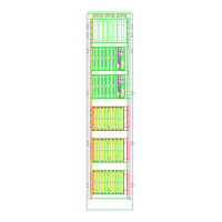
Bus Extender Unit Module IOP371
Metso Automation MAX Controls Inc. • 277596 •
11-11
BEM Configuration Considerations
Communication between the DPU and the remote I/O occurs in real time
using the existing Model IOP protocol. The remote I/O modules
communicate with the DPU, as if they were local I/O. Extenders are
transparent to the bus.
Although the BEM extends the Model IOP I/O bus up to 2000 meters, a time
delay factor reduces the maximum number of I/O modules that may be
installed beyond 400 meters. The time delay in the Extender circuit is
minimal; however there is a delay in the optical cable, introduced by the
speed of light, which is proportional to distance (approximately 1 x 10
-
9
sec/ft).
In configurations using a cable link no more than 400 meters in length, I/O
module reduction is minimal. See "Calculating Link Capacities."
Calculating Link Capacities
While as noted, a DPU supports up to 60 I/O per location, a link delay exists
proportional to distance. The Extender circuits themselves introduce very
little delay.
The distance factor primarily impacts Digital Input modules set for SOE
operation. The following table shows the maximum number of DI modules,
which can be handled at various cable distances. This is caused by the need
to scan all SOE cards every 1 ms.
For example, at 2,500 feet a DPU 4E can have 14 DI modules set for SOE.
No other restrictions limiting the number of cards exist. For instance, the
number of thermocouple or analog cards does not decrease because of
distance.
Of course, the 60 cards on an electrical DPU Bus still apply.
The microsecond numbers reflect the total amount of time, including the
speed of light for the signal to be sent and to return, for each card's
transactions.
Table 2. Number of Modules Supported by Distance
Meters Feet DPU 4A/4B
maximum
SOE cards
DPU4E
maximum
SOE cards
0 0 22 32
8 25 22 32
61 200 20 28
152 500 18 24

 Loading...