maxPAC Hardware Reference Guide
Metso Automation MAX Controls Inc. • 277596 •
7-2
scanned by the DPU. A second green LED provides the status of the loop
power fuse disconnect.
Bus Address
This module requires one I/O one bus address. The address range for digital
input modules is 0 – 1F (0-31).
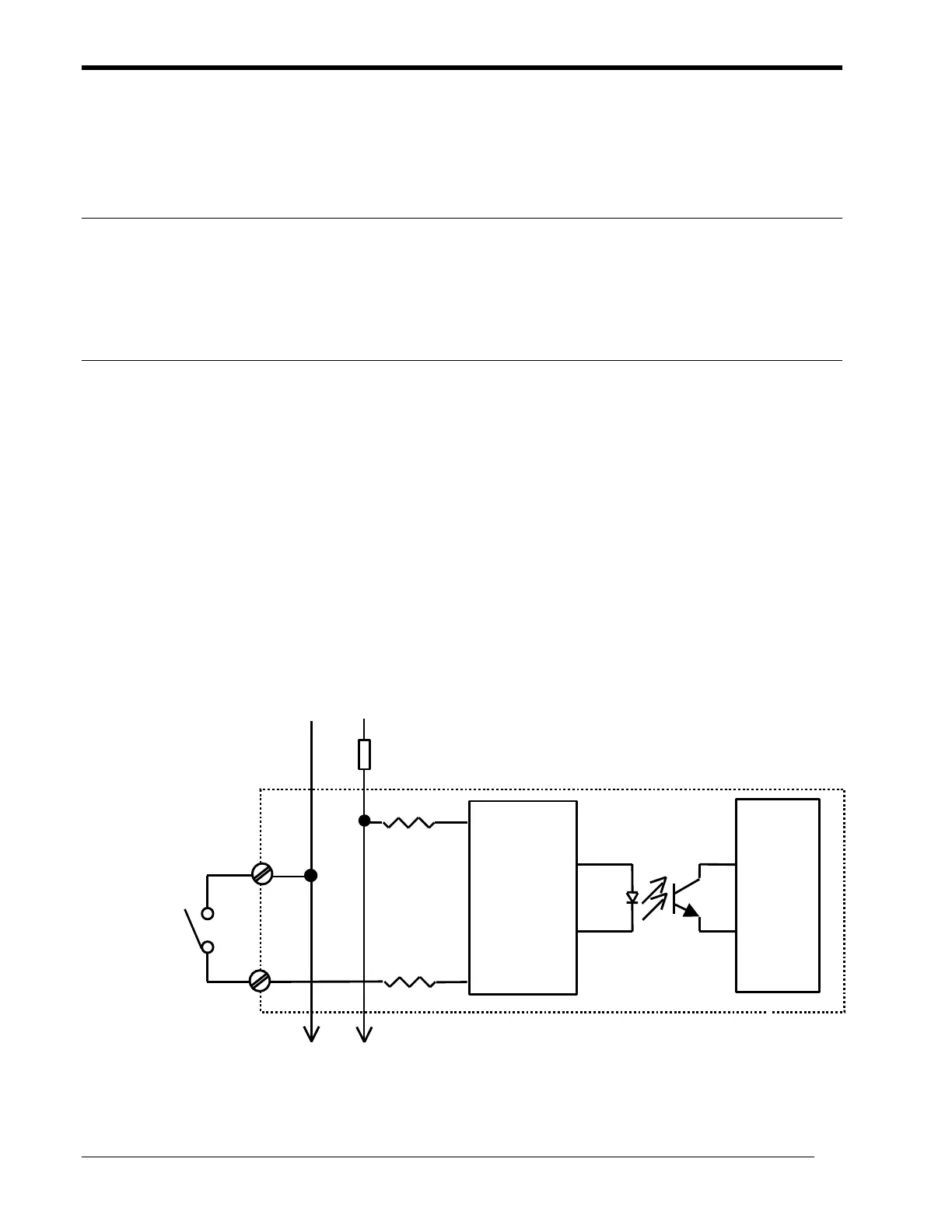
Module Operation
The following is a simplified sketch of the circuit for one channel. The
signal-conditioning block provides filtering, current limiting circuit, and an
input threshold. It also includes the input status LED. The optical isolator
provides isolation between the field circuits and the logic circuits. The input
status is buffered and latched in the I/O bus interface circuit. The data is
presented to the I/O bus as a 16-bit word when the module is scanned by the
DPU. A watchdog timer in the I/O bus interface circuit controls the
operation of the active LED, causing it to blink when the module is not
scanned for 0.7 seconds.
The 24V/48V(+) and 24V/48V(-) loop power signals are connected to all the
channels. They are routed to the module from the backplane via a fuse
disconnect which is accessible from the front of the module.
To other channels
Signal
Conditioning
Circuit
I/O BUS
Interface
Circuit
Fuse disconnect