Do you have a question about the metso automation maxPAC and is the answer not in the manual?
Introduction to the maxPAC Input/Output System and its DPU link.
Details on cabinets, chassis assemblies, and I/O module types.
Describes the three chassis assembly types and mounting procedures.
Explains the APS Power Supply Assembly and its features.
Details local and remote field cable termination approaches.
How to set addresses for I/O modules using rotary switches.
Discusses shared, redundant, and mixed input/output configurations.
Introduces the Bus Extender Unit for I/O bus expansion.
Details environmental, I/O bus, and input/output specifications.
Introduction to the IOP301 module's 16 isolated input channels.
Explains microprocessor operation, A/D conversion, and calibration.
Provides detailed technical specifications for the IOP301 module.
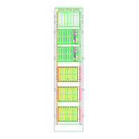
Illustrates field wiring connections for the IOP301 module.
Introduction to IOP302 (4-20mA) and IOP305 (Voltage) modules.
Explains microprocessor operation, A/D conversion, and calibration.
Provides detailed technical specifications for IOP302 and IOP305.
Illustrates field wiring connections for IOP302 and IOP305 modules.
Introduction to the IOP303 module's 8 isolated 3-wire RTD input channels.
Explains microprocessor operation, A/D conversion, and calibration.
Provides detailed technical specifications for the IOP303 module.
Illustrates field wiring connections for the IOP303 module.
Introduction to the IOP304 module's 16 thermocouple/emf input channels.
Explains microprocessor operation, A/D conversion, and calibration.
Provides detailed technical specifications for the IOP304 module.
Illustrates field wiring connections for the IOP304 module.
Introduction to the IOP320 module's 8 4-20 mA output channels.
Explains microprocessor operation, output signal generation, and watchdog timer.
Provides detailed technical specifications for the IOP320 module.
Illustrates field wiring connections for the IOP320 module.
Introduction to IOP330 (24V) and IOP331 (48V) digital common input modules.
Explains circuit, signal conditioning, and data presentation.
Provides detailed technical specifications for IOP330 and IOP331.
Illustrates field wiring connections for IOP330 and IOP331 modules.
Introduction to isolated digital input modules IOP332, IOP333, and IOP334.
Explains circuit, signal conditioning, and data presentation.
Provides detailed technical specifications for IOP332, IOP333, and IOP334.
Illustrates field wiring connections for IOP332 and IOP333 modules.
Introduction to the IOP335 module's 8 Pulse I/O digital input channels.
Details supported functions like Frequency Input and Event Counter.
Provides detailed technical specifications for the IOP335 module.
Illustrates field wiring connections for the IOP335 module.
Introduction to IOP350 (Form C) and IOP351 (Form A/B) relay modules.
Explains relay driver operation, output LEDs, and watchdog timer.
Provides detailed technical specifications for IOP350 and IOP351.
Illustrates field wiring connections for IOP350 and IOP351 modules.
Introduction to the Bus Extender Unit for I/O distribution and expansion.
Explains transmitter, receiver, and CPLD functions of the BEM.
Covers DPU compatibility, bus loading, and redundant configurations.
Discusses link availability, detection, cabling, and specifications.
| Brand | metso automation |
|---|---|
| Model | maxPAC |
| Category | Home Automation |
| Language | English |