maxPAC Hardware Reference Guide
Metso Automation MAX Controls Inc. • 277596 •
1-8
Sequence of Mounting Operations
Mounting the parts of the Model IOP I/O in proper order can save time and
duplication of effort.
Follow this sequence as closely as possible for best results:
1. Refer to field wiring instructions that can influence mounting locations
for chassis assemblies and chassis assembly/module replacement.
2. Mount the chassis assemblies; see "Mounting I/O Chassis Assemblies."
3. Perform all steps as outlined in "Cabling, Power, and Ground Wiring."
5. Complete field wiring.
6. Refer to "Module Addressing" for switch settings and jumper selections.
7. Install I/O modules.
If your field wiring enters through the bottom of the cabinet, mount the
Model IOP I/O units from top to bottom. This will make wiring of future
units easier, since you will not have to pull wires from the bottom of the
cabinet past existing Model IOP I/O units. This same reasoning applies to
field wiring entering the top of the cabinet. Here you mount the Model IOP
units from bottom to top.
Mounting I/O Chassis Assemblies
The Model IOP I/O chassis assembly attaches to the rear mounting rails in
standard 19-inch maxDNA I/O cabinets. Three chassis styles are available.
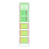
See “Chassis Assembly.” Up to seven chassis assemblies may be installed in
a standard cabinets.
Usually, the Model IOP I/O units are supplied already mounted in cabinets,
but if you are mounting them yourself, follow this procedure.
Note: before you mount an I/O chassis, it should contain the I/O backplane.
To attach the chassis assembly:
1. At the desired chassis assembly mounting location in the cabinet, place
eight 10-32 nut retainers (MAX Part No. 003530) in the rear mounting
rail holes that correspond to the eight screw slots on the Model IOP
chassis assembly.
2. The holes in the maxDNA cabinet rear mounting rails are arranged in a
repeating pattern of two holes close together separated by a single hole.