Analog Input Modules
4-20mA Input Module IOP302
Voltage Input Module IOP305
Metso Automation MAX Controls Inc. • 277596 •
3-7
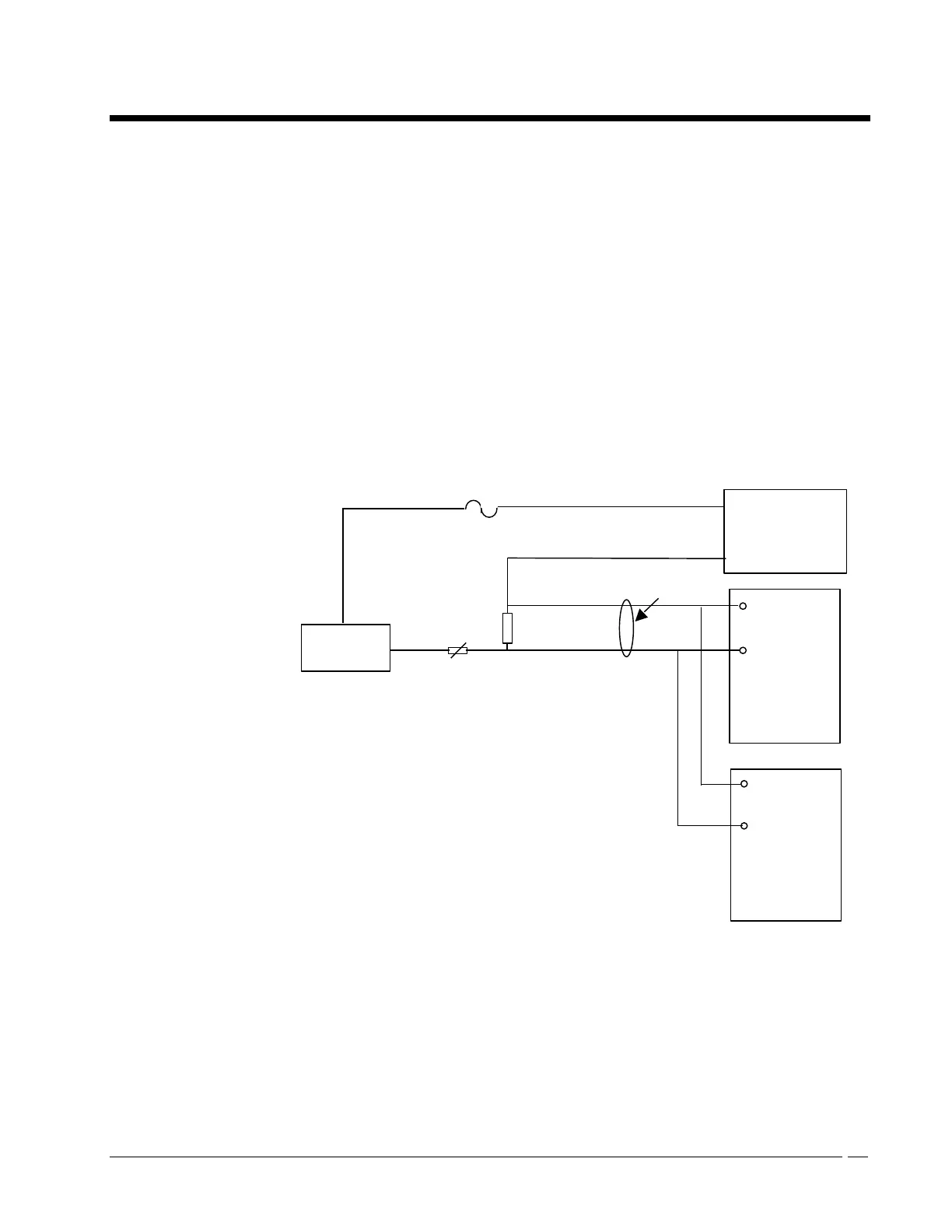
Field Wiring For Redundant Modules with Common Transmitter
The following figure shows the recommended wiring for two redundant
IOP305 analog input channels that share a common transmitter.
The recommended maximum distance between the shunt resistor and the I/O
module is 10 meters. The +24V connection is independently fused to each
transmitter. The voltage that is developed across each 100-Ohm shunt by the
4-20 mA signal from the transmitter is wired to the AI module using twisted
pair cables.
The (-) terminal of the loop supply is connected to the (-) side of the shunt
resistors so that the 4-20 mA current does not flow through the twisted pairs
wires. A PTC thermistor is recommended between the transmitter output and
the 100-Ohm shunt. This protects the 100-Ohm shunt against over voltage
and provides additional resistance to increase the transmitter load to 250
Ohms. Kit IOP306 supplies 16 pairs of 100-Ohm shunts and thermistors to
support two IOP305 analog input modules.
thermistor
(+)
DCS 24V
Loop Supply
(-)
(+)
Primary
IOP305
AI Module
Transmitter
2-wire
(-)
(+)
Secondary
IOP 305
AI Module
100