Page 37
Mechanical Installation
thermoMETER CTL
6. Mechanical Installation
6.1 Sensor
i
Keep the optical path free of any obstacles. For an exact alignment of the sensor to the object activate
the integrated double laser, see 9.4.
The CTL is equipped with a metric M48x1.5 thread and can be installed either directly via the sensor thread
or with help of the supplied mounting nut (standard) and fixed mounting bracket (standard) to a mounting
device available.
Avoid mechanical violence on the sensor.
> Destruction of the system
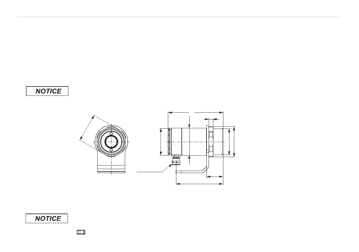
85.5
(3.37)
Ø49.3
(1.94 dia.)
M48x1.5
WS 52
30
(1.18)
8 (.31)
Cable gland
M 12 x 1.5
Ø55
(2.17 dia.)
100 (3.94)
Ø50
(1.97 dia.)
Fig. 3 Dimensions CTL sensor
Dimensions in mm, not to scale
Make sure to keep the optical path clear of any objects.
> Deviation of measured value, inaccurate measurement result
For an exact alignment of the head to the object, please activate the integrated double laser, see 9.4.