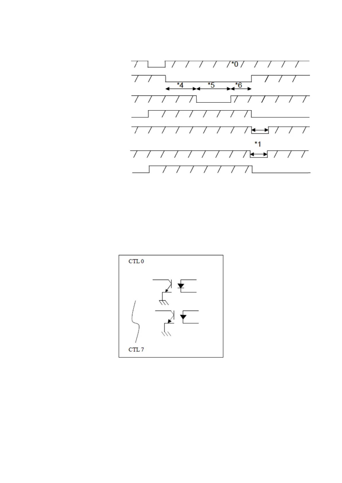
*0 Output high potentials require pull-up resistors to achieve; the voltage can reach a maximum of
30V.
*1 Pulse holding time output can be set to 1ms-1000ms.
*2 Activate test when there is low potential.
*3 Hold until the next round of testing has started.
*4 The length of this interval is set according to the pretest items of the high voltage test.
*5 There is the only output when AC/DC high voltage is enabled.
*6 The length of this interval is set according to the post-test items of the high voltage test.
The above is the output waveform for a single test file when defined as all tests completed; details
are set according to the test file.
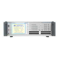
5. CTL0 - CTL1 internal circuit diagram is as shown in the figure below: