Do you have a question about the Microtest 8740 and is the answer not in the manual?
Overview of safety signs used in the manual and on the instrument.
Prohibition of unauthorized internal modifications and adjustments to the machine.
Guidelines to prevent machine damage from static electricity.
Importance of proper grounding to prevent electrical shock.
Specifications for power cables, connectors, and input voltage.
Recommended warm-up period for optimal tester accuracy.
Instructions for addressing instrument malfunctions and repairs.
Guidance on powering off the machine when not in use.
Recommendations for operating and storing the machine.
Procedures for electrical shock or fire emergencies.
List of standard accessories included with the 8740 series cable tester.
Explanation of notations and symbols used throughout the user manual.
Details on alphanumeric input, cursor movement, and core button functions.
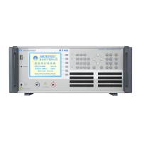
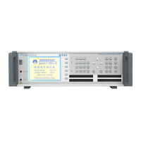
Identification and description of components on the tester's front panel.
Identification and description of components on the tester's rear panel.
Visual representation of the tester's functional flow and interconnections.
Step-by-step instructions for installing and starting the 8740 series tester.
Detailed explanation of the functions of various button groups.
Overview of the main functions available for system operation.
Procedure for executing the self-test function upon powering on.
Accessing and viewing machine and software version details.
Adjusting DC high voltage readings to match setting values.
Adjusting AC high voltage readings for accurate AC setting values.
Executing internal resistance offset action for the machine.
Details on optional fixture calibration for the constant current box.
Displaying the current output pin by connecting a probe.
Configuring protocol, IP, and server port for networking.
System configuration and test-related action settings.
Configuring environment parameters like power-on self-test and language.
Configuring test environment parameters like tester ID and alarms.
Adjusting the system's year, month, day, hour, minute, and second.
Procedure for changing the system password for key lock protection.
Instructions for direct printer output of data and screens.
Setting short circuit conditions by learning cable connection.
Reference to Chapter 4 for detailed file management information.
Viewing test result statistics like total tests, passes, and failures.
Overview of different test modes and entering TEST MODE.
Procedure for learning DUT pins and setting up MultiDUT mode.
Selecting specific test items within the test mode.
Setting control standards and test conditions for DUTs.
Setting the short circuit table for OPEN/SHORT test conditions.
Setting conductance parameters like max, min, offset, and mode.
Editing parameters for Resistance, Capacitance, and Diode tests.
Setting parameters for DC insulation and AC tolerance tests.
Performing simultaneous and automatic tests.
Performing tests in real-time using saved test conditions.
Loading saved files from memory for testing.
Managing files for ease of use, including selection, deletion, and sorting.
Loading saved files from permanent memory to main memory.
Setting specific test steps for a DUT to simplify processes.
Function to create a new file in the permanent memory.
Uploading a selected file from tester to USB flash drive.
Uploading all files from the tester to the USB flash drive.
Permanently deleting files saved on the permanent memory.
Sorting files according to specified rules.
Importing files from a USB flash drive to the tester.
Wiring configuration details for the RS-232C cable.
Wiring configuration for the printer cable (25-PIN and 36-PIN).
Wiring configuration and pin definitions for the 15-PIN remote cable.
Diagrams illustrating remote output waveforms for various signals.
Overview of test ranges and functions for different measurement types.
Detailed technical specifications of the 8740 series tester.
History of version updates and modifications for the software.
| Power Source | Rechargeable Battery |
|---|---|
| Wire Map | Yes |
| Remote ID | Yes |
| Frequency Range | Up to 350 MHz |
| Display | LCD |
| Standards Compliance | ISO 11801 |
| Data Storage | Yes |
| Length Measurement | Yes |
| Supported Cables | Coax |