49
4.1.3 R/C/D Component Setting Edit (Resistance)
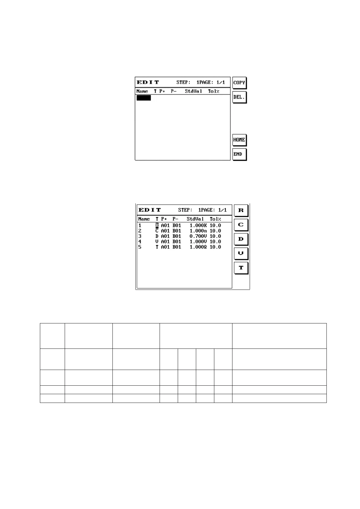
(1) Press the [R/C/D] button and the screen will display as follows:
(2) After entering the name, move the cursor to line T and then use S1 S2 S3 to select test capacitance
C, resistance R, and diode D.
(3) The voltage (V) function must be used with the 8740 CC3 constant current box (purchased
optionally), and only the following points can be used to perform cable voltage drop/impedance
test. Point operation restrictions are as described in the table below.
(4) When users pay more attention to the precision of the cable voltage drop and the impedance,
connect all DUTs first, then use the short cable (internal resistance less than 10mΩ) to short-
circuit the red and black terminal in front of the constant current box and then press offset. When
the test current is changed, offsetting is recommended in order to measure the more accurate data.
When the 8740 host is used with the 8740 CC3 constant current box to perform cable voltage drop test,
use of a genuine fixture adapter board is recommended; if users need to use their own adapter board,
please beware of the PIN definitions of the DUT and the PIN definitions in the previous table, as well
as the operation restrictions. In order to measure the most accurate voltage drop and ensure that the
DUT was not tested out of spec, prevent over-current from causing damage to the cable/contact due to
overload.
Setting the current for more than 4A is mainly used for low resistance (under 0.2Ω) tests; users must
beware that the enabling of the loop is different from under 4A (included). This will give different test