System interconnections 9
DL431 Mic Splitter
Operator Manual
System interconnections
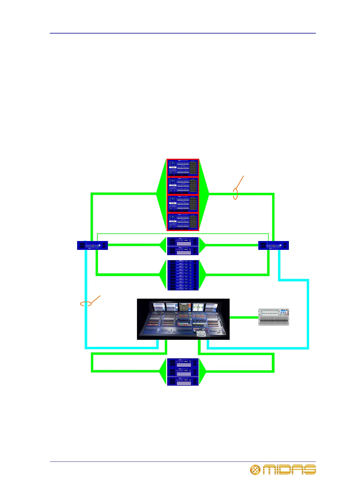
Figure 1 shows basic system interconnectivity and indicates where the four DL431 Mic
Splitter units (highlighted in red) sit within the system. This figure also illustrates
redundancy by showing that the two halves of the system - left and right - are identical
(ignoring the DN9331 RAPIDE).
Each of the DL431 Mic Splitter units are directly connected to both routers.
The XL8 Control Centre, which forms the core of the XL8 Live Performance System, is
connected to each router via a ‘snake’ and also connects to a DN9331 RAPIDE. Each
router acts as a hub by linking the majority of the system components together, all of
which are common to both halves of the system.
The network carries both proprietary control data and open architecture AES50 digital
audio, and uses readily available standard Cat5, Cat6/fibre optic cabling and
connectors.
Figure 1: Basic interconnectivity of a standard XL8 Live Performance System
Cat5 cabling
Cat6/optical
‘snake’
Local I/O units
DSP units
Mic splitters
I/O units
Router
Router
XL8 Control
Centre
DN9331 RAPIDE