Connecting up the XL8 11
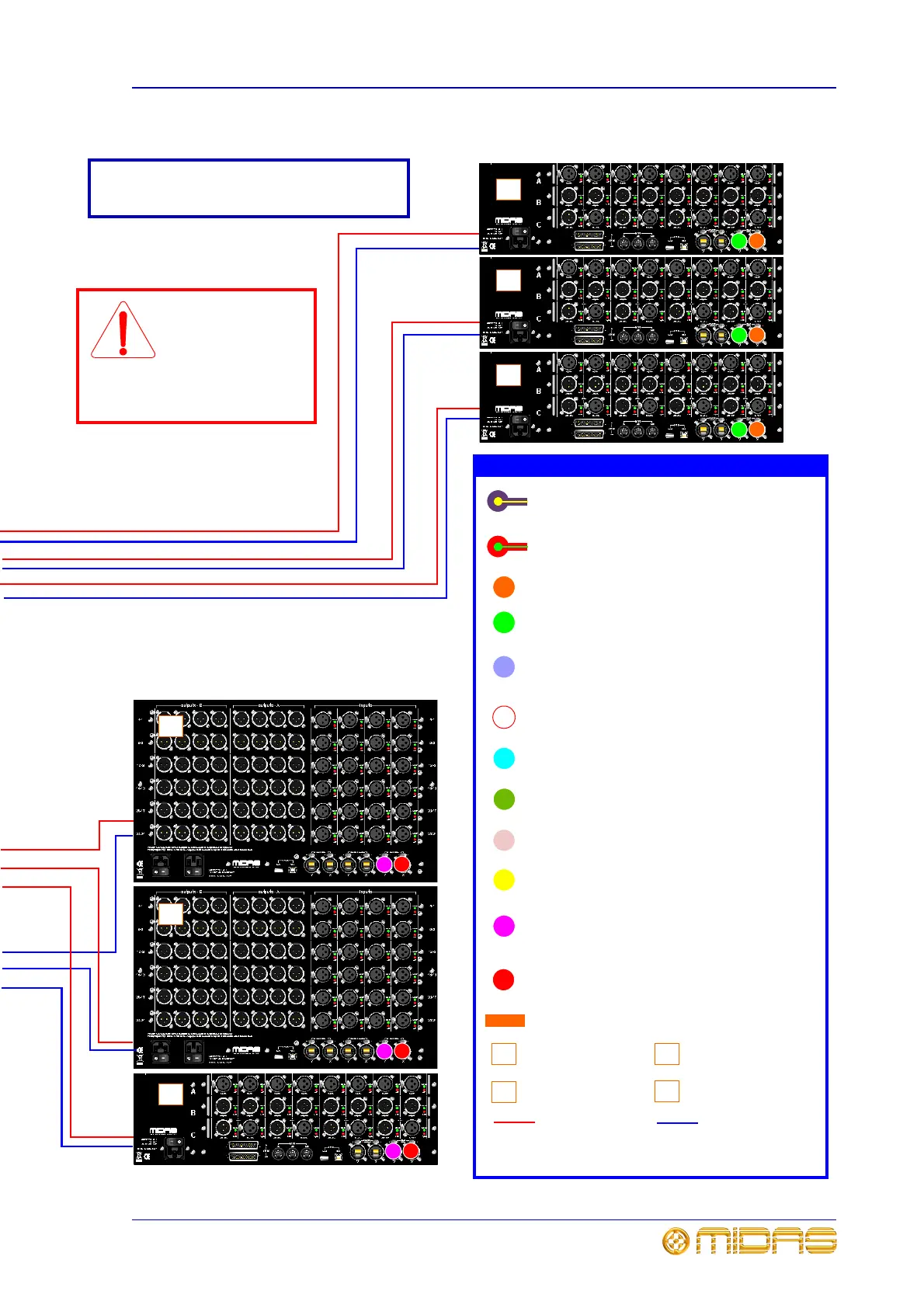
DL431 Mic Splitter
Operator Manual
X router’s AES50 audio - bank 1 connectors to
AES50 audio - A X connector on mic splitters and
AES50 audio X connector on I/O boxes
Control centre AES50 audio Y connectors to
FOH rack I/O unit AES50 audio Y connectors
33
44
66
A
A
B
1
1
1
1
1
1
1
1
1
1
Stage rack 3
Control centre AES50 audio X connectors to
FOH rack I/O unit AES50 audio X connectors
Control centre snake/optical X and Y
connectors to appropriate X or Y router’s
snake/optical connector
Control centre snake/CAT6e X and Y
connectors to appropriate X or Y router’s
snake/CAT6e connector
X router’s AES50 audio - bank 0 connectors
to AES50 audio X connector on DSP units
Y router’s AES50 audio - bank 0 connectors to
AES50 audio Y connector on DSP units
X router’s Ethernet control connectors to
Ethernet control X connectors on DSP units
Y router’s Ethernet control connectors to
Ethernet control Y connectors on DSP units
Y router’s AES50 audio - bank 1 connectors to
AES50 audio - A Y connector on mic splitters and
AES50 audio Y connector on I/O boxes
A
Mic splitter
B
I/O box
Link DSP backbone (cables linking connectors
1-1 and 6-6 are non-standard lengths)
1
C
DSP unit
D
Router (X and Y)
Main cable
Duplicate cable
Note: Cable descriptions can be found in “Cable type and
function” on page 12.
Key
Note:
For connections specific to the 19” rack units, please
refer to their respective operator manuals
Router interconnection across the Ethernet tunnel
external 2 connectors. System snake
redundancy will be compromised without it!
22
11
B
B
FOH rack
33
B
Caution!
Don’t forget the
interconnection
between the two
routers, as system snake
redundancy will be
compromised without it.
RapidE “ETHERNET” connector to X or Y
external 2 (Ethernet tunnel connector) on
the control centre