27
www.roadwidener.com
Model SPD-6
6. Toggle blade grade switch (A) downward to lower
strike off blade to the ground.
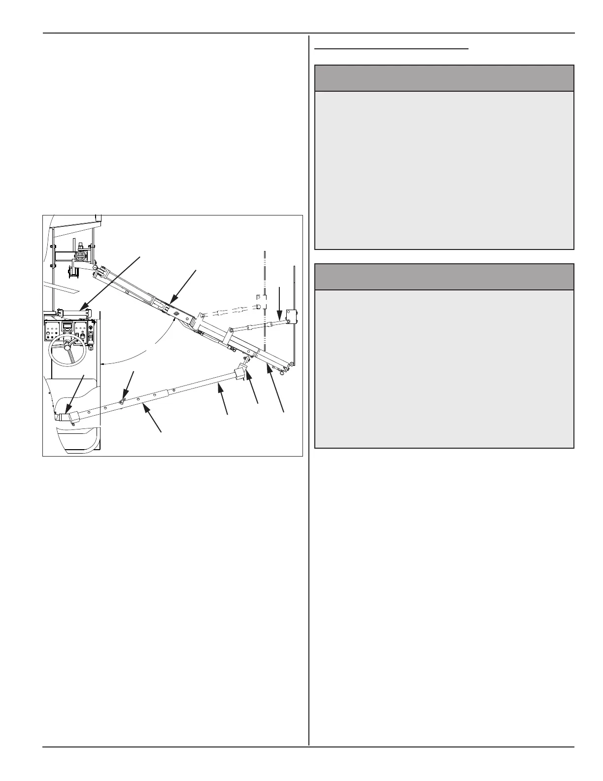
7. Insert inner push tube (C) into outer push tube (D).
8. Connect push tubes ends to push tube mounts on
blade (E) and chassis (F).
9. Insert center pin (G) at the closest concentric holes
on outer and inner push tubes when at desired
blade paving angle. Push tube mount (E) on the
blade must be mounted at approximately ½ to ⅔ of
blade length.
60°
C
D
F
E
G
I
L
K
J
Note: Depending on the material, a greater blade angle
may be needed to ll the entire spread width. Narrower
spread widths do not require as much blade angle.
10. Slope cylinder mounting lug (L) on the blade must
be at approximately ⅔ length of entire blade length.
11. Adjust edger brace (turnbuckle) (K) and pin in place
so outer edger plate is parallel to the lane edge or
inner edger.
12. Toggle grade switch (A) and slope switch (H) for
the desired shoulder prole. Keep in mind material
compaction if the job will be rolled.
13. Toggle hydraulic blade extension (B) switch to
make instantaneous changes to blade length.
5.4 CHAnGe BlAde lenGtH
^ WARNING
Prevent serious injury or death.
Before performing adjustments,
inspections, service or maintenance:
• Park machine on rm, level surface and
engage parking brake.
• Switch engine off.
• Close and lock control panel cover.
• Chock tires.
• Place “Do Not Operate” tag on
operators console.
^ WARNING
Prevent serious injury or death.
Blade components are heavy.
Use an adequate lifting device to raise, lift
and move blade and blade components.
1 Foot blade section - 45 lbs.
2 Foot blade section - 75 lbs.
Outer Edger Assembly - 70 lbs.
Hydraulic Extension Assembly - 185 lbs.
Procedure illustrates blade on right side. Procedure is
the same for left side blade.
1. Perform Startup Procedure. See section 5.2. Park
machine on a rm level surface, engage parking
brake by pushing operator console E-stop button
fully down. Keep engine running at full rpm.
2. Lower blade to ground.
3. Switch engine off.
4. Close and lock control panel cover.
5. Remove push tube assembly (A) from push tube
mount on blade.
6. Disengage slope control cylinder (B) from blade.
7. Remove push tube mount (C) and slope mount(D).