VetPro DC Installation/Service Manual, 00-02-1606, Revision R01
129
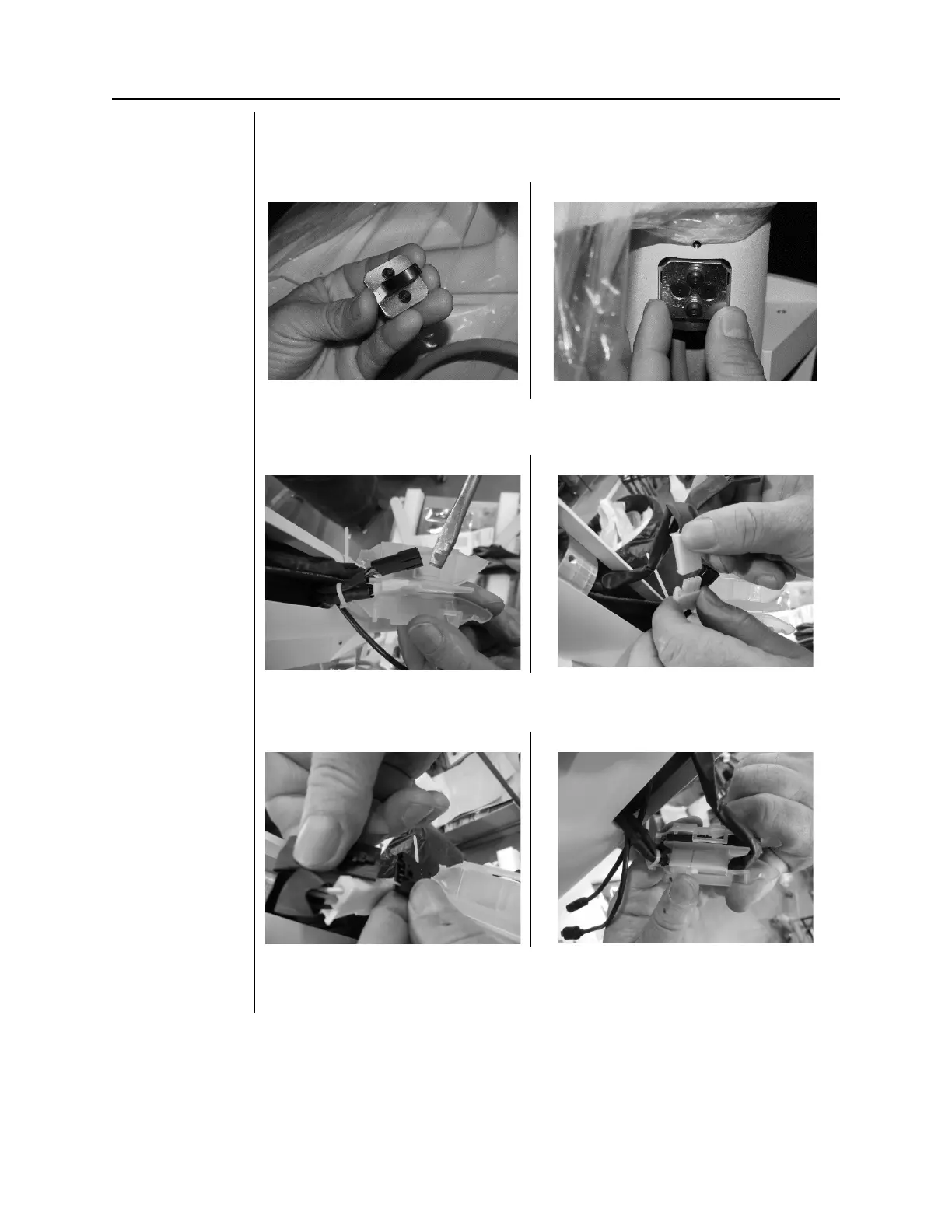
13. Locate and install the articulating arm brake assembly. Install and adjust
by tightening to the point where the articulating arm does not drift when
you lightly push the arm
Figure 133
14. Pry apart the Isolator containing the connectors for the cables. Connect
the power cables (white connectors).
15. Connect the feedback cables (black connectors). Insert cables into the
Isolator, one on each side of the divider and snap shut.
16. If the unit is a VetPro Complete (Sensor ready), connect the USB cables.
Insert cables into the post.