VetPro DC Installation/Service Manual, 00-02-1606, Revision R01
90
Produced
and No
Audible
Exposure
Indicators
Two different audible exposure indicators are employed within the VetPro DC system.
One indicator is embedded in the Operator Panel and will initiate when any exposure
switch is pressed. The second audible indicator initiates when the Logic Board
begins the exposure sequence. During normal operation, first the Operator Panel
indicator will sound followed shortly thereafter by the Logic Board indicator. It is
important to recognize the sequence for troubleshooting purposes.
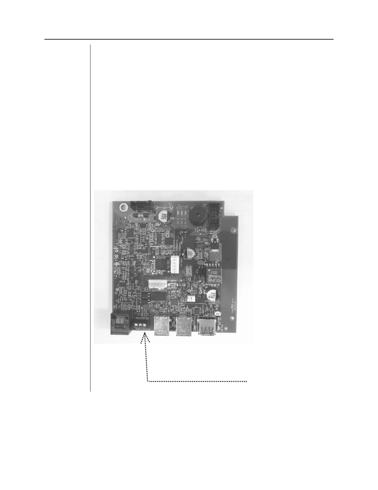
1. If the Operator Panel indicator does not sound, inspect the condition of any
remote exposure switches. Substitution is the preferred method to test these
switches, although a jumper wire can be applied across the contacts of J2,
shown in
Figure 69
, on the Logic Board momentarily to simulate an exposure
switch closure.
2. If the Operator Display indicator sounds, but the Logic Board indicator does not
activate, observe LED D2 on the Power Supply Board, and listen for the relay LS1
to activate on this same board (
Figure 70
). LED D2 should illuminate during the
exposure request. If not, inspect the condition of the ribbon cable between the
Power Supply and the Logic Boards. If the ribbon cable is acceptable, replace
the Logic Board.
Figure 69
Logic Board
30-08160
J2 Remote Exposure Switch Connector