TS571W Installation Instructions 13
E
A
B
C
D
F
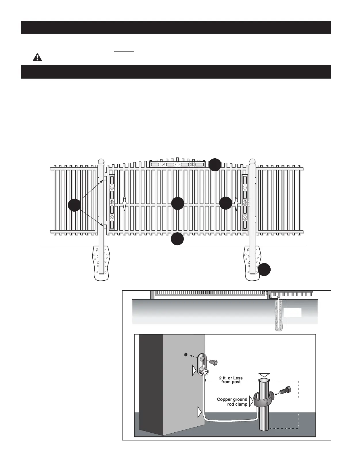
Gate Grounding
● For reference only.
Cooper Clad Ground Rod
(not included)
Use an 8 foot, 5/8 inch ground rod,
positioned two feet or less from the
post and 2 inches or less above the
ground. Available at local home center
or hardware stores.
NOTE: No grounding system absolutely
protects against lightning strikes. If
installed correctly, a grounding system
will help minimize damage to your gate
operator.
● The gate must be plumb, level, and swing freely on its hinges.
● The gate must move throughout its arc without binding or dragging on the ground.
● Wheels must NOT be attached to the gate.
● Gates over 250 lb. should have ball bearing hinges with grease ttings.
● Post must be secured in the ground with concrete (minimizes twist/ex when the operator is activated).
● Make sure there is a stable area for mounting the gate bracket (this may require the addition of a horizontal or vertical cross
member).
● We recommend you position the operator near the center-line of a gate to keep the gate from twisting and exing, and to
avoid back-splash from rain.
Copper clad ground rod
(not included)
Ground
Ground
2 Inches or
Less above
ground
Copper ground
rod clamp
Copper Single
Conductor Lug
3/16” Drilled
Pilot Hole
6 ft. deep
or more
Metal Gate Post
12awg or Larger
2 ft. or Less
from post
IMPORTANT: CHECK FOR PROPER GATE INSTALLATION
CHECK EXISTING GATE SIZE AND MATERIAL
• Gate size: Up to 18 feet and up to 850 lbs. — See
Operational Capacity chart on page 11.
Not rated for use on solid surface gates.
• Type of gate material: Vinyl, aluminum, chain link,
farm tube, wrought iron, wood.
- Plumb
- Free Swinging
- Secured Posts in
E - Center line Mounting
F - Good Working Hinges (ball bearing
hinges are recommended on gates
over 250 pounds)