TS571W Installation Instructions 33
TRANSFORMER OR SOLAR PANEL WIRING INSTALLATION
GRN
WHT
BAT+
AUTO
CLOSE
RESET
PULL
STAGGER
WARNING
BAT–
GRN
WHT
RED
BLK
RED
BLK
COM
COM
CYCL
SAFE
EXIT
SHDW
AUX
V+
AUX
V-
LOCK
V+
LOCK
V-
CLOSE
EDGE
OPEN
EDGE
PRIMARY
SECONDARY
LOCK AUX
SW1
SW2
PUSH
12345
+
TERM6
AUTO
CLOSE
RESET
PULL
STAGGER
WARNING
COM
COM
CYCL
SAFE
EXIT
SHDW
CLOSE
EDGE
OPEN
EDGE
PUSH
12345
+
GRN
WHT
BAT+
BAT–
GRN
WHT
BRN
ORG
RED
BLK
SECONDARY
SW1
SW2
TERM6
Operator Arm Cable/Power Access
Alternate Access
+
–
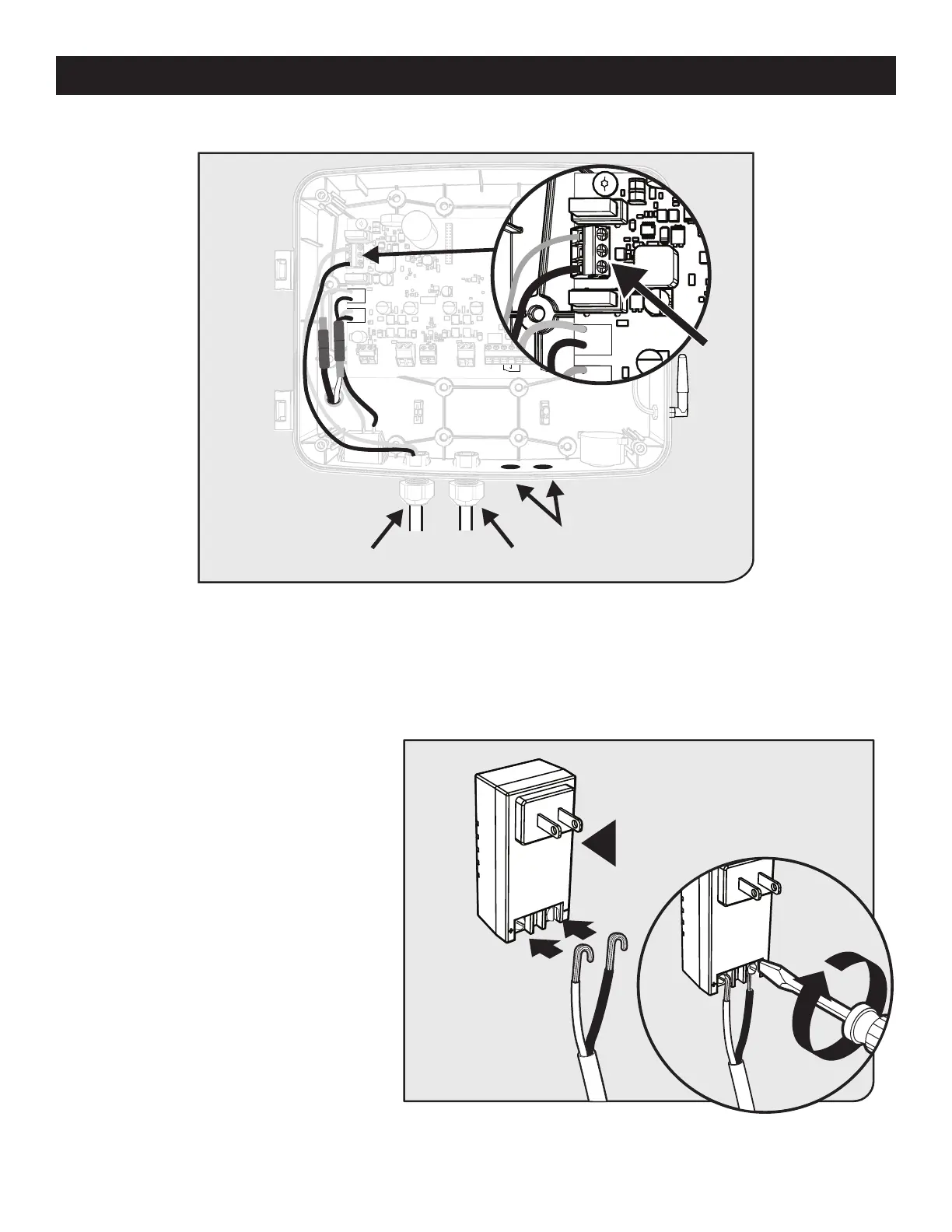
● Feed the transformer or solar panel wires into the control box using one of the access locations on the bottom of the box.
● Connect the RED wire to PWR+ and the BLACK wire to PWR- on TERM 6 as shown.
Step 3
Step 4
C
GRN
WHT
BAT+
AUTO
CLOSE
RESET
PULL
STAGGER
WARNING
BAT–
GRN
WHT
RED
BLK
RED
BLK
COM
COM
CYCL
SAFE
EXIT
SHDW
AUX
V+
AUX
V-
LOCK
V+
LOCK
V-
CLOSE
EDGE
OPEN
EDGE
PRIMARY
SECONDARY
LOCK AUX
SW1
SW2
PUSH
12345
+
TERM6
GRN
WHT
BAT+
BAT–
GRN
WHT
BRN
ORG
RED
BLK
RED
BLK
AUX
V+
AUX
V-
PRIMARY
SECONDARY
SW1
SW2
TERM6
Battery Power Access
BATT– BATT+
+
+
–
–
● From the other end of the low voltage wire,
strip 1/2” from both the RED and BLACK
wire.
● On the transformer, connect RED wire to
the screw terminal marked + and BLACK
wire to the screw terminal marked -.
● Plug the transformer into the selected
electrical outlet.
Note: Use of a surge protector is strongly
recommended.