General
OM-244 814 Page 31
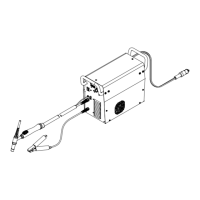
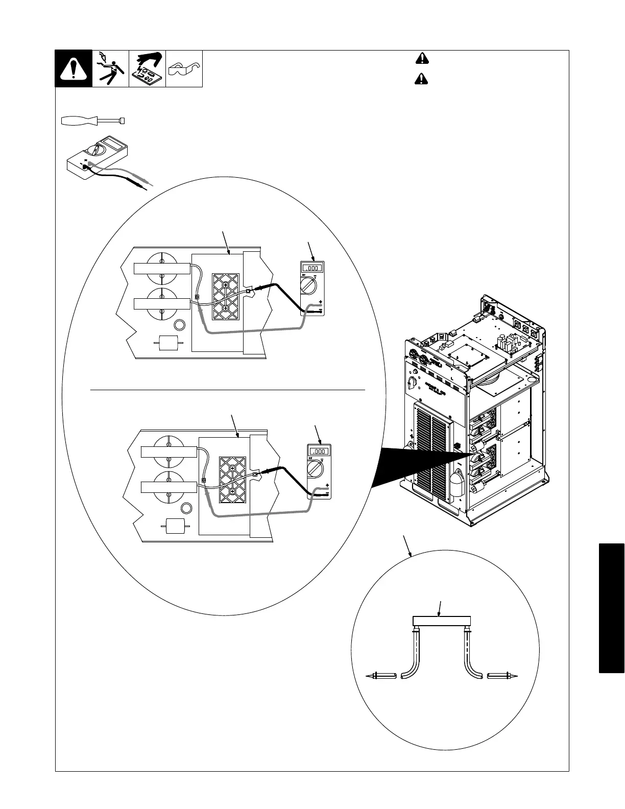
8-9. Removing Cover and Measuring Input Capacitor Voltage
! Turn Off welding power source,
and disconnect input power.
! Significant DC voltage can
remain on capacitors after unit is
Off. Always check the voltage as
shown to be sure the input ca-
pacitors have discharged before
working on unit.
Remove cover
1 Interconnect Board PC2
2 Voltmeter
Measure the DC voltage across the +
bus terminal and − bus terminal on PC2
as shown until voltage drops to near 0
(zero) volts. Measure input capacitor
voltage on both inverter assemblies
before proceeding.
3 Typical Bleeder Resistor
An example of a typical bleeder resistor
is shown on this page.
Proceed with job inside unit. Reinstall
cover when finished.
Tools Needed:
5/16 in.
802 985 / Ref. 245 768-A
1
2
+ lead to left bus terminal, − lead to right bus terminal
1
2
+ lead to left bus terminal, − lead to right bus terminal
3
Typical Bleeder Resistor
#16 AWG 1000 volts DC
insulation rating, approx
3 in. (76 mm) leads
25 to 1000 ohm,
5 watt resistor