General
OM-244 814 Page 39
Ref. 245 744-A
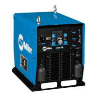
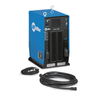
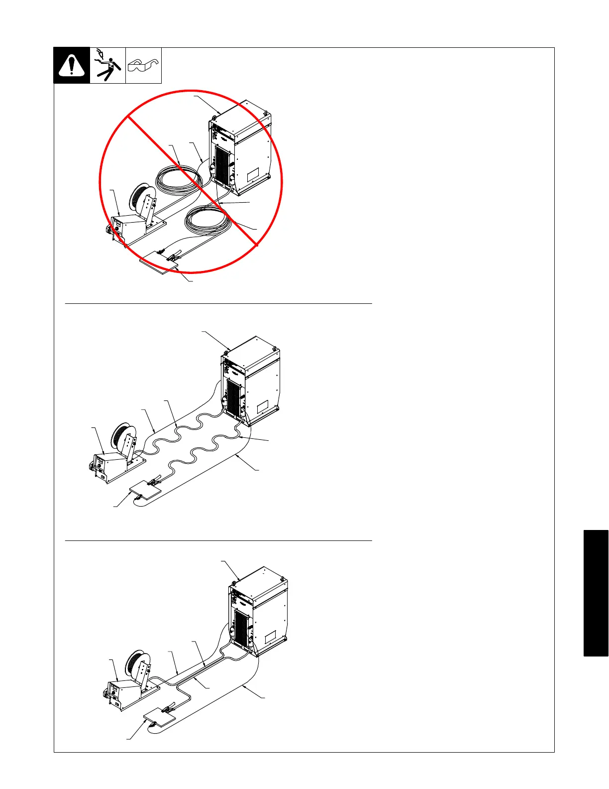
1 Welding Power Source
2 Electrode Cable
3 Feeder Cable
4 Work Cable
5 Voltage Sensing Lead
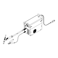
6 Wire Feeder
7 Workpiece
The arrangement of the cables has an
effect that is significant to the welding
properties. As an example, Accupulse
welding process can produce high
welding circuit inductance depending
on cable length and arrangement. This
can result in limited current rise during
droplet transfer into the welding puddle.
The electrode sense lead is contained
in the feeder control cable and
automatically becomes enabled for all
semi-automatic processes. The work
sense lead connects to the Axcess
welding power source 4-pin connector
located above the negative output
terminal. This work sense lead
automatically compensates for work
cable voltage drop when connected to
the welding power source.
Do not coil excess cables. Use cables
that are the appropriate length for the
application. Whenever using long weld
cables [longer than 50 ft (15 m)] try to
arrange positive and negative weld
cables together to reduce the magnetic
field surrounding the cables. Avoid
coupling the feeder and work sense
leads with the weld cables.
9-4. Arranging Welding Cables To Reduce Welding Circuit Inductance
Bad
Better
Best
1
2
6
5
4
3
7
1
2
3
4
5
6
7
1
5
4
2
3
6
7