15.1 Digital control output
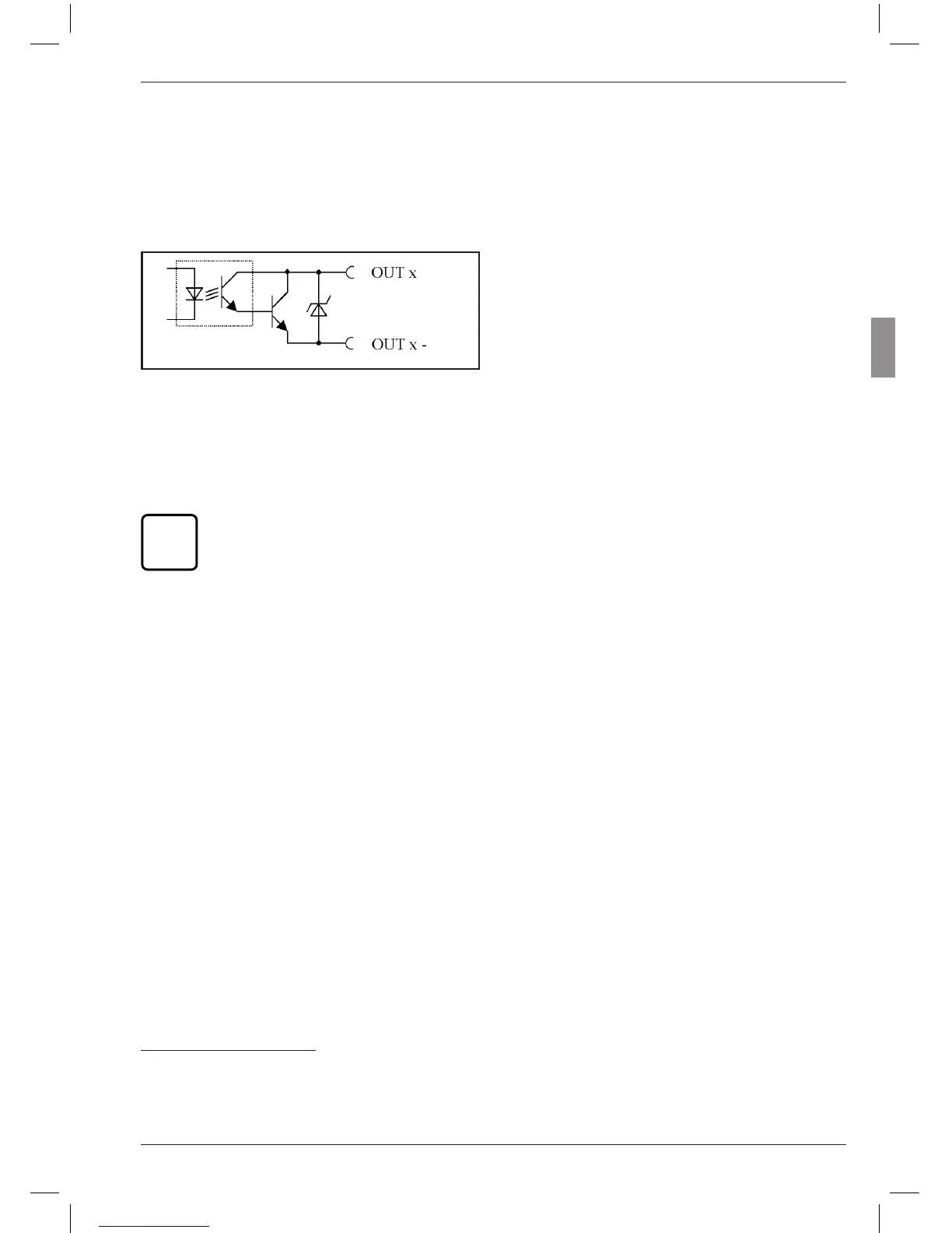
Circuit diagram of an output:
Fig. 8
Circuit diagram of an output from the parallel
(I/O) interface
Digital control output modes:
MODE 0
No signals are sent to the outputs. Always
select this setting when the digital control
outputs are not to be used.
MODE 1
A1 = Signal „Measurement in progress“
A2 = Signal „Measurement complete“
A3 = Signal „Measurement OK“
MODE 2
A1 = Signal „Measurement OK“
A2 = Signal „Measurement outside
warning limit“
A3 = Signal „Measurement outside
tolerance“
MODE 3
A1 = Signal „OK“
A2 = Signal „Rework“
A3 = Signal „Reject“
MODE 4*
Enables the Millitron 1840/SG control unit to
be connected.
A1 = Signal „OK“
A2 = Signal „Rework“
A3 = Signal „Reject“
MODE 5
A1 = Signal "Measurement OK”
A2 = Signal “Measured value < lower warn-
ing limit”
A2 = Signal “Measured value > upper
warning limit”
*
If MODE 4 is selected for the input signals, MODE 4 is
also set for the output signals and vice-versa.
The preset functions (modes) can be
assigned to the digital control outputs
either via the Millimar or via the Win-
dows based configuration program
D1000S.