Mahr GmbH, Millimar C1208/C1216/1240
Fig. 10
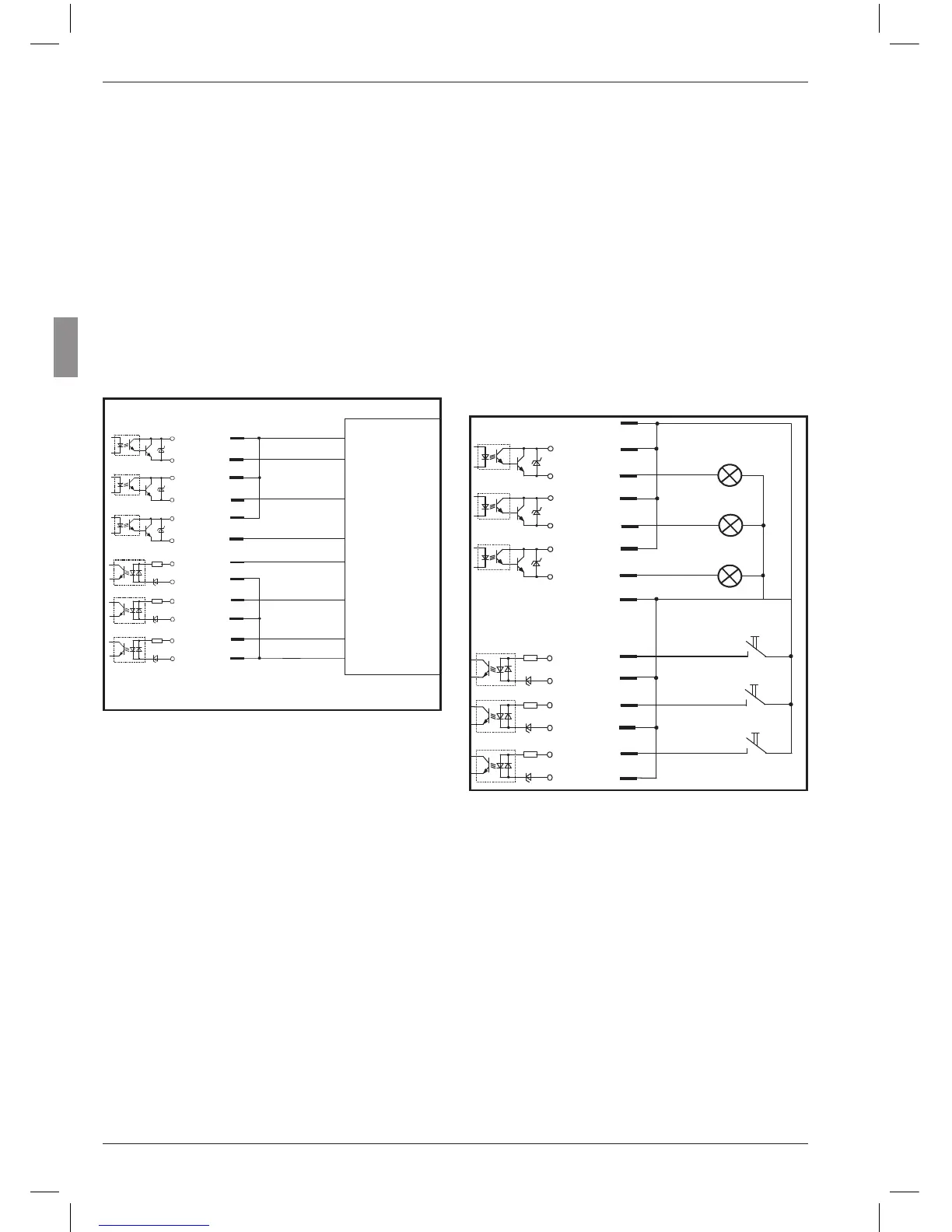
Connecting a programmable controller
Example 2: Connecting to a device without
its own power supply
The internal auxiliary voltage of Millimar can be
used when connecting switches or lamps to it.
However in such cases, galvanic isolation is only
ensured when the connected device ensures this
isolation.
Fig. 11
Connecting lamps for classifying measurement
results
20
22
23
24
21
25
5
6
8
9
11
OUT3+
OUT3-
OUT2-
OUT1-
OUT2+
OUT1+
IN3+
IN2+
IN1+
IN1-
IN2-
IN3-
Output
Output
Output
Input
Input
Input
0 V
+24 V
SPC
Cable
25 pin Sub-D
connector
12
20
22
23
24
21
25
4
5
6
8
9
11
12
Cable
OUT3+
OUT3 -
-
OUT2
-
OUT1 -
OUT2+
OUT1+
IN3+
IN2+
IN1+
IN1
-
IN2
-
IN3
-
9 V, max. 100 mA
0 V
15.3 Application examples for the use of
digital control inputs and outputs
Example 1: Connection to a programmable
controller
When Millimar is connected to a programmable
controller, the supply voltage of the programma-
ble controller should provide the necessary cur-
rent through the optocouplers in order to ensure
potential separation.