PL-565 Accumass BW500 Page 15
Installation
mA I/O board
The BW500 is software/hardware ready to accept the optional mA I/O board. The
mA I/O board provides 2 programmable 0/4-20 mA outputs, 2 programmable 0/4-20
mA inputs and a nominal 24V dc supply for loop powered devices.
Your BW500 may be shipped to you without an mA I/O board, for installation at a
later date.
If you are ready to install your mA I/O board, please follow the instructions as
outlined.
Installation
1. Isolate power and voltages applies to the BW500
2. Open the lid
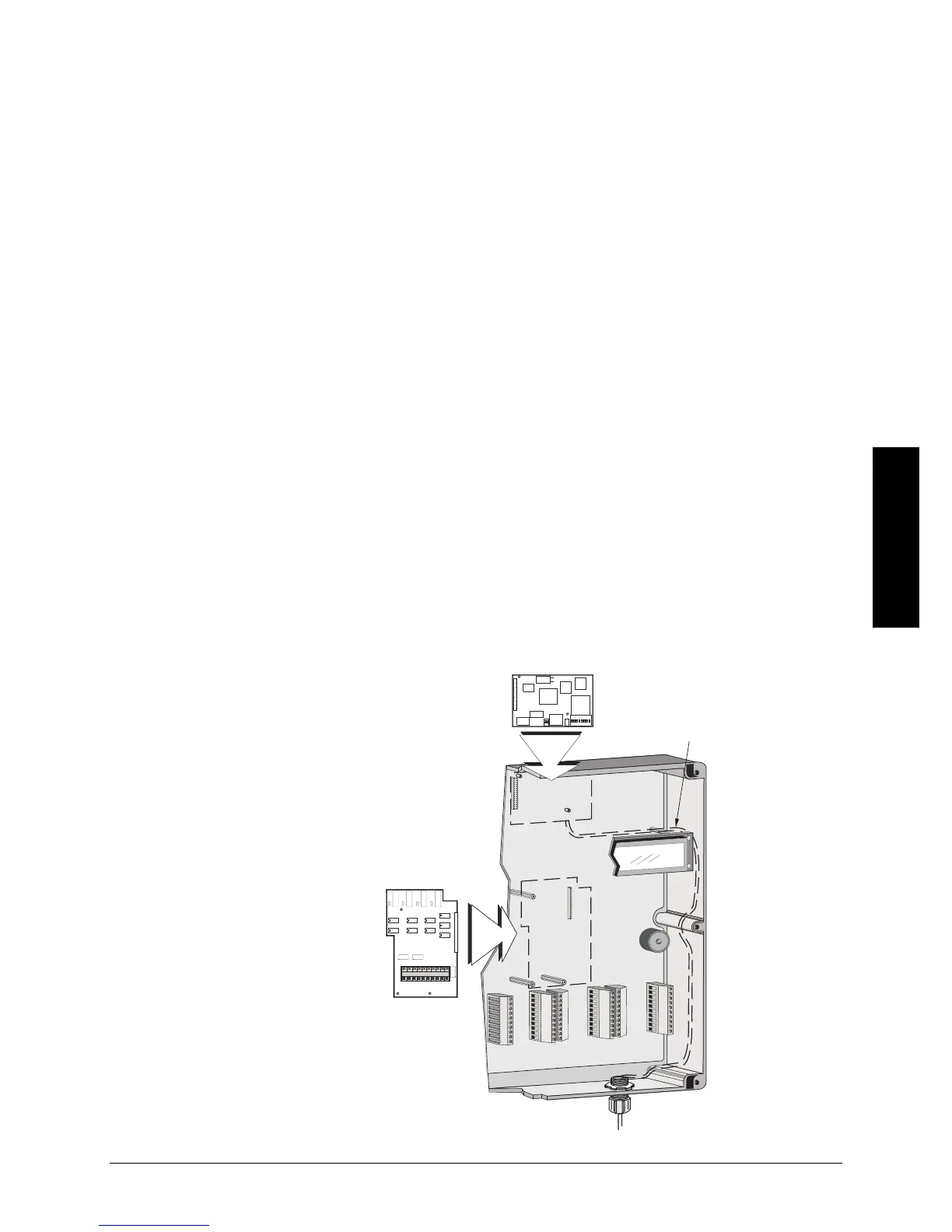
3. Install the board by mating the connectors and secure the card in place using the 3
screws provided.
4. Close the lid
5. Apply power and voltage to the BW500.
Refer to:
• Specifications on page 9
• mA I/O board on page 15
• mA I/O Parameters (P200 - P220) on page 65
• mA I/O (0/4-20 mA) in the Operation section on page 91
SmartLinx
®
mA I/O board
route SmartLinx
®
cable
along right hand wall
 Loading...