Page 16 Accumass BW500 PL-565
Installation
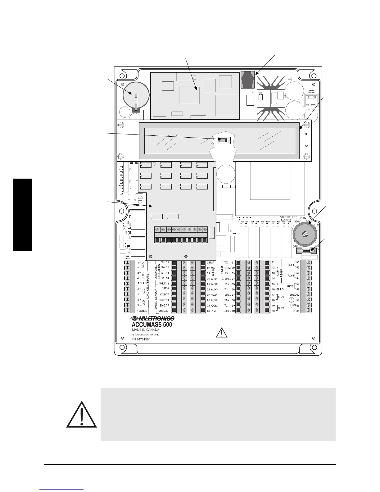
Layout
*To reduce communication interference, route SmartLinx
®
cable along right side of
enclosure wall.
• All field wiring must have insulation suitable for at least 250 V.
• dc terminals shall be supplied from SELV source in accordance with IEC
10101-1 Annex H.
• Relay contact terminals are for use with equipment having no accessible live
parts and wiring having insulation suitable for at least 250 V
• The maximum allowable working voltage between adjacent relay contact shall
be 250 V.
certification
switch
optional
Analog I/O
board
battery,
memory
back up
optional SmartLinx
®
module*
display
board
power
switch
port 3
(RJ-11)
fuse
FU1