EasyManuals Logo

Mindray DC-70 Pro User Manual

Mindray DC-70 Pro
295 pages
To Next Page IconTo Next Page
To Previous Page IconTo Previous Page
Page #160 background imageLoading...
Page #160 background image
9-22 Structure and Assembly/Disassembly
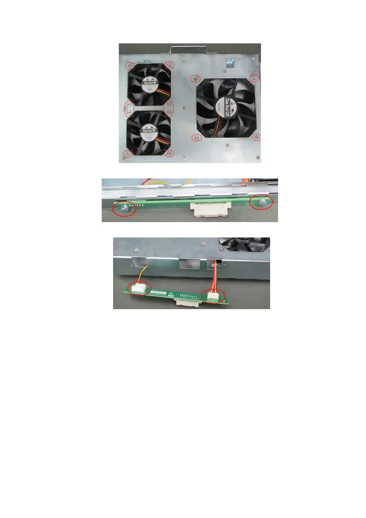
4. Unscrew two M3 step screws fixing PCBA, and remove fan PCBA.
5. Pull out of the fan socket to remove the fan.
9.3.14 Motherboard
The disassembly tool: cross-headed screwdriver (M3, M4), diagonal cutting pliers, anti-electrostatic
glove.
1. Follow step 1 to step 3 in Chapter 9.3.2 to remove the left/right side panels and the front cover.
2. Refer Chapter 9.3.2 to unscrewing the probe assembly.
3. Refer Chapter 9.3.6 to unscrewing the rear cover and IO assembly.
4. Refer Chapter 9.3.9 to Chapter 9.3.11 to removing DC box assembly, PC assembly, engine
board and TR board.
5. Unscrew the M4 X 8 grounding screw on the right side of the device.

Table of Contents

Questions and Answers:

Question and Answer IconNeed help?

Do you have a question about the Mindray DC-70 Pro and is the answer not in the manual?

Mindray DC-70 Pro Specifications

General IconGeneral
Touch ScreenYes
Touch PanelYes
Transducer Ports4
Battery BackupYes
3D/4D ImagingYes
Operating SystemWindows-based
Power Supply100-240V AC, 50/60 Hz
Storage500GB HDD
ConnectivityUSB, HDMI
ApplicationsCardiology, Obstetrics, Gynecology
Imaging ModesColor Doppler, Power Doppler
PortsUSB, Ethernet, HDMI
Display Size19 inch

Related product manuals