9-28 Structure and Assembly/Disassembly
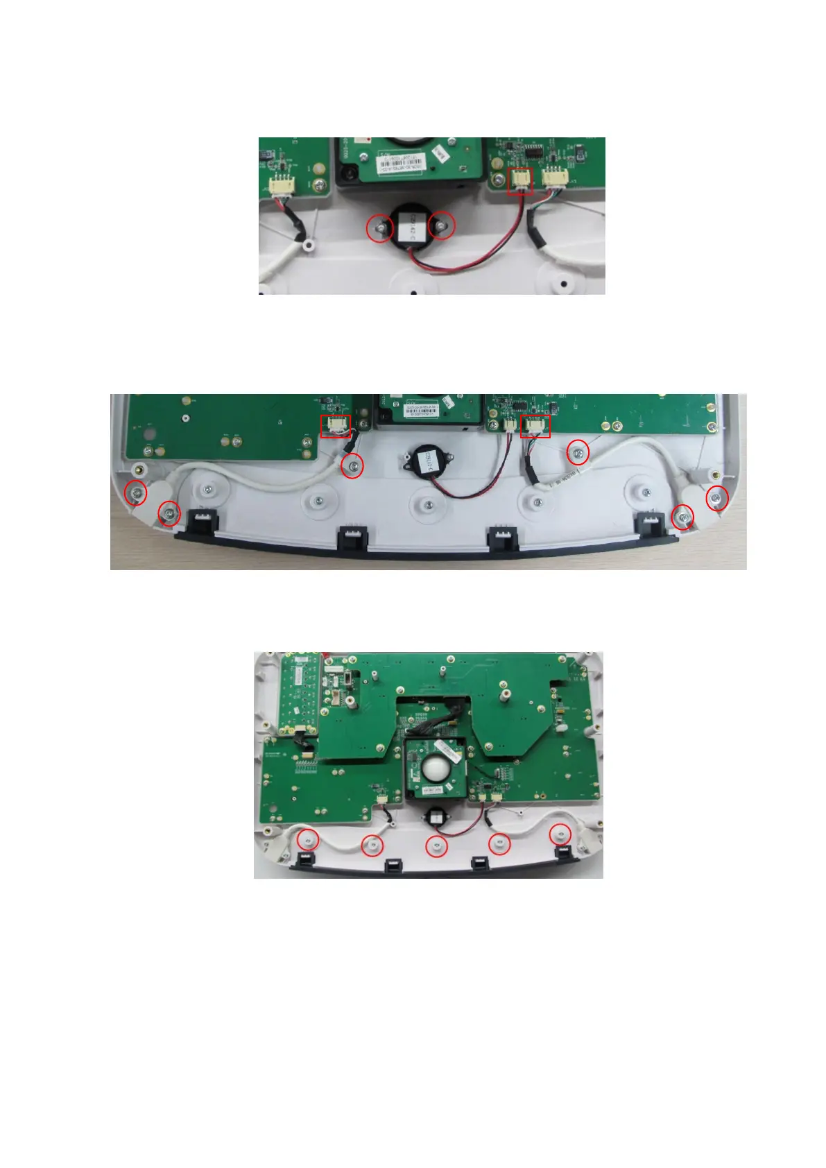
Unscrew two PT2 X 6 tapping screws and gaskets to remove the buzzer. Disconnect the plug of the
buzzer to remove it.
9.3.15.5 USB Cable
The disassembly tool: cross-headed screwdriver (M3, M4), anti-electrostatic glove
Unscrew two PT3 X 10 tapping screws from USB and the M3 X 8 SEMS screw from the clip.
Disconnect USB cables to remove them (one cable on each side).
9.3.15.6 Support Mat
The disassembly tool: cross-headed screwdriver (M3, M4), anti-electrostatic glove
Unscrew five PT3 X 10 tapping screws from the support mat to remove it.
9.3.15.7 Upper Cover of the Keyboard and Control Panel Board
The disassembly tool: cross-headed screwdriver (M3, M4), anti-electrostatic glove
1. Remove the encoder assembly, trackball assembly, TGC board and the buzzer.
2. Unscrew M3 X 8 SEMS screw from the grounding cable. Remove the upper cover of the
keyboard and the control panel board.