EasyManuals Logo

Mindray DC-70 Pro User Manual

Mindray DC-70 Pro
295 pages
To Next Page IconTo Next Page
To Previous Page IconTo Previous Page
Page #184 background imageLoading...
Page #184 background image
9-46 Structure and Assembly/Disassembly
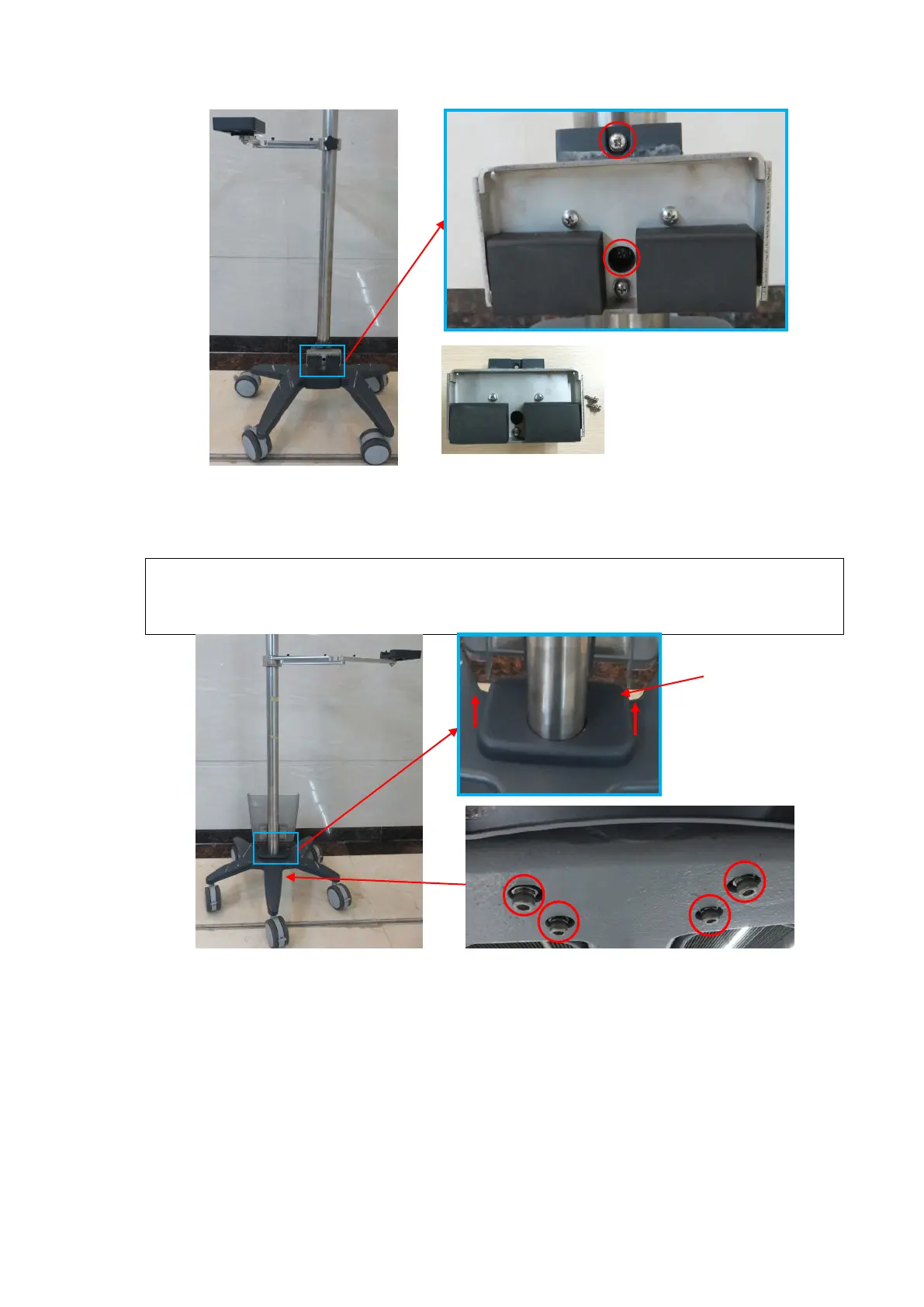
9.3.28.3 Bottom Cover
1. Remove the shield cover from the fixture. Unscrew the M6 X 30 (*4) round inner head screws
(with the pad) with M6 spanner to lift the upper part of the standing pole.
Note:
In case of the scratch to the base assembly when removing the standing pole,
check whether the shield cover is lifted completely.
In case of injury to the personnel, hold the standing pole when untightening the
inner screws.
2. Unscrew M6 X 20 (*5) round inner head screws (with pads) with the M6 screwdriver to remove
the bottom cover.
Shield cover
Trolley bottom view
C
onnecting base assembly
(FRU)

Table of Contents

Questions and Answers:

Question and Answer IconNeed help?

Do you have a question about the Mindray DC-70 Pro and is the answer not in the manual?

Mindray DC-70 Pro Specifications

General IconGeneral
Touch ScreenYes
Touch PanelYes
Transducer Ports4
Battery BackupYes
3D/4D ImagingYes
Operating SystemWindows-based
Power Supply100-240V AC, 50/60 Hz
Storage500GB HDD
ConnectivityUSB, HDMI
ApplicationsCardiology, Obstetrics, Gynecology
Imaging ModesColor Doppler, Power Doppler
PortsUSB, Ethernet, HDMI
Display Size19 inch

Related product manuals