21-572 21-572
21.11.3. Layout condition edit
Click the [Edit] button at [Condition] at "Properties". The "Layout object condition edit" screen is displayed.
Figure 21-96 Layout condition editing
You can display or hide layout objects by specifying I/O conditions for corresponding layout objects. This function
can be used in simulation.
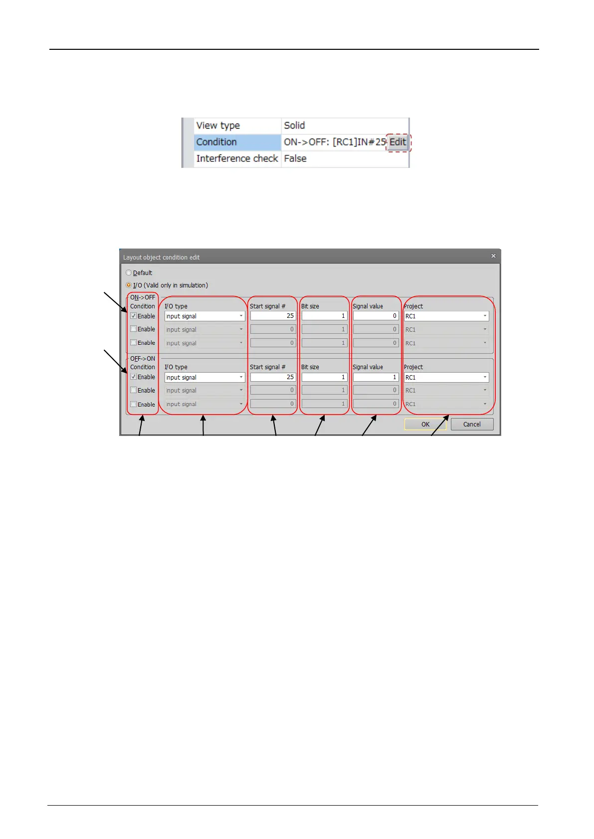
Figure 21-97 Layout condition edit
If you set no condition, select [Default]. If you set some conditions, select [I/O (Valid only in simulation)].
This sets the conditions for changing target layout objects from a displayed to a
hidden state. Up to three conditions can be specified. When all conditions are
satisfied, the layout object is hidden.
This sets the conditions for changing target layout objects from a hidden to a
displayed state. Up to three conditions can be specified. When all conditions are
satisfied, the layout object is displayed.
If you checked [Enable], you can set the condition.
Check same number to set conditions.
Select [input signal], [output signal], [Register (CC-Link) Input], [Register (CC-Link)
Output].
Set 0 or larger when you select [input signal] or [output signal].
Set 6000 or larger when you select [Register (CC-Link) Input] or [Register (CC-Link)
Set 1 - 32 when you select [input signal] or [output signal].
Set 1 - 2 when you select [Register (CC-Link) Input] or [Register (CC-Link) Output].
Set the value which is compared with I/O state.
Set the unsigned decimal value which is expressed in binary value with bit size
specified (6) when you select [input signal] or [output signal].
Set the signed decimal value which is expressed in binary value with 1 register (16 bit)
or 2 register (32 bit) specified (6) when you select [Register (CC-
Link) Input] or
[Register (CC-Link) Output].
Specifies the target project (robot) to check I/O conditions.
 Loading...


