448
28 FUNCTIONS
28.2 System Switching
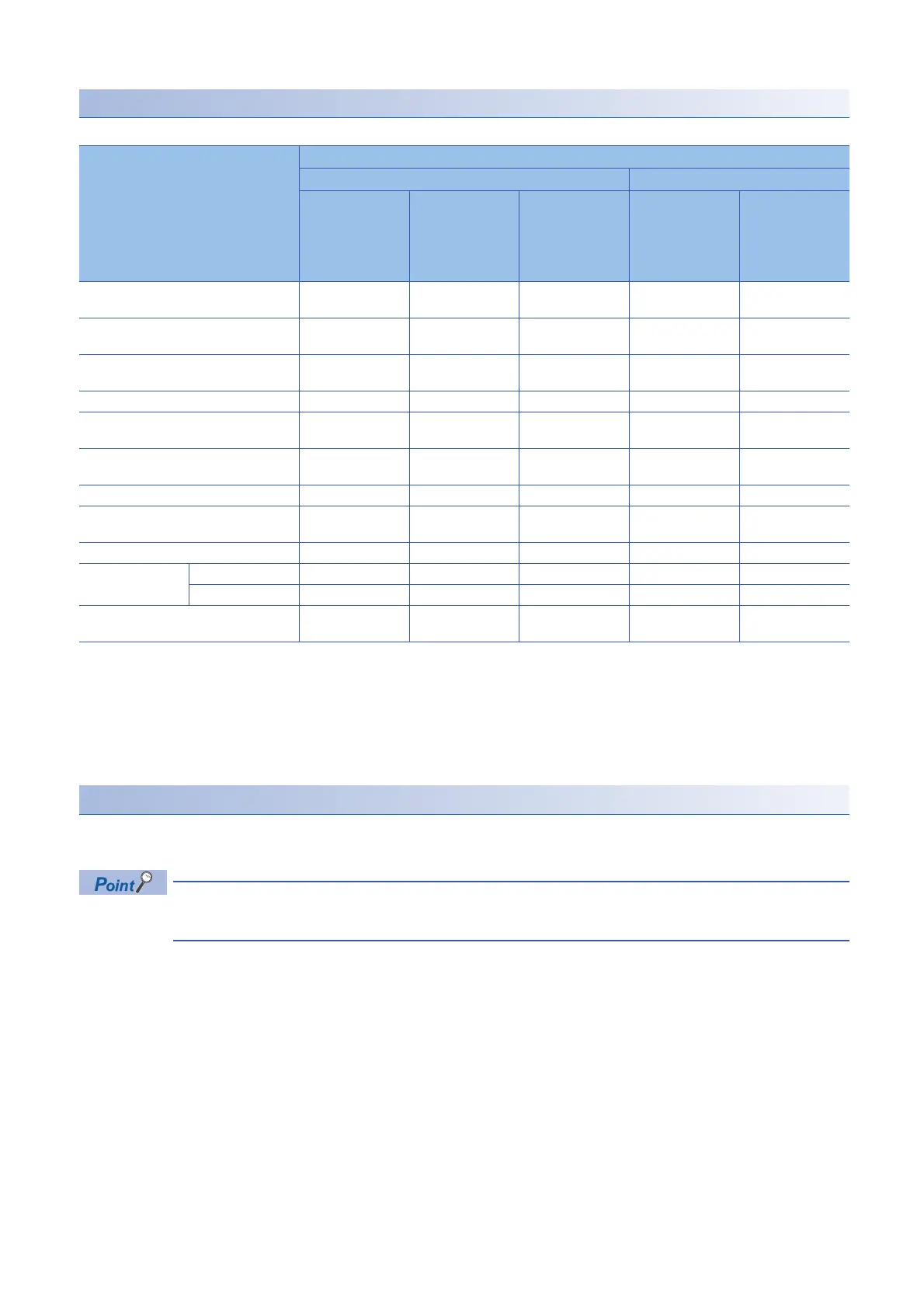
In separate mode
: Switching possible, : Switching not possible
*1 When the group specification has been set in the standby system, a network error is not detected if communication is available with the
line of an Ethernet-equipped module after a communication error has occurred on the other Ethernet-equipped module. ( MELSEC
iQ-R Ethernet User's Manual (Application))
*2 If system switching is failed when a system switching request is sent, a continuation error occurs and a cause of a switching failure is
stored in SD1644 (Cause of system switching failure).
*3 If system switching is disabled when a system switching request is sent, the error code corresponding to a cause of the system
switching failure is returned.
Occurrence of a cause of the system switching failure
When a cause of the system switching failure occurs, the BACKUP LED flashes in backup mode and the SEPARATE LED
flashes in separate mode.
The cause to flash the BACKUP LED or SEPARATE LED can be checked in SD1642 (BACKUP/SEPARATE
LED flashing cause). Check SD1642 and eliminate the cause to flash the LED.
Redundant system status Execution availability of system switching
Automatic system switching Manual system switching
Power-off, reset,
hardware failure
of the CPU
module
Stop error of the
CPU module
System
switching
request from a
network module
System
switching
request by the
SP.CONTSW
instruction
*2
System
switching
request from the
engineering
tool
*3
Normal operation or continuation error in
the standby system
Tracking communications disabled (cable
disconnection)
Power-off, reset, hardware failure of the
standby system CPU module
Stop error in the standby system
Network error detected in the standby
system
*1
During memory copy from control system
to standby system
During online change
Mismatch between the CPU module
operating status of both systems
During system switching
During online
module change
Redundant module
Other modules
System switching disabled by the
DCONTSW instruction

 Loading...

