888
APPX
Appendix 7 List of Safety Special Register Areas
SA\SD1104
to
SA\SD1223
Safety
communication
status of each
safety connection
(1st to 8th module)
Safety connection
No. 1 to 120
Safety
communication
status of safety
connection numbers
1 to 120
• The safety communication status of safety connections of the
module stored in SA\SD1089 is stored.
• 0 is stored if not used in SA\SD1104 to SA\SD1223, or if own station.
0H: Performing safety refresh communications
10 to 15H: Performing safety initial communications
*2
30H: Safety communication stopped (This value is stored when
the safety communication error occurs and the systems are
switched in interlock status.)
1000H or later:For details on the values stored when an error
occurs, refer to the list of error codes. ( Page 703 List of error
codes)
S (Status
change)
RnPSF
RnSF
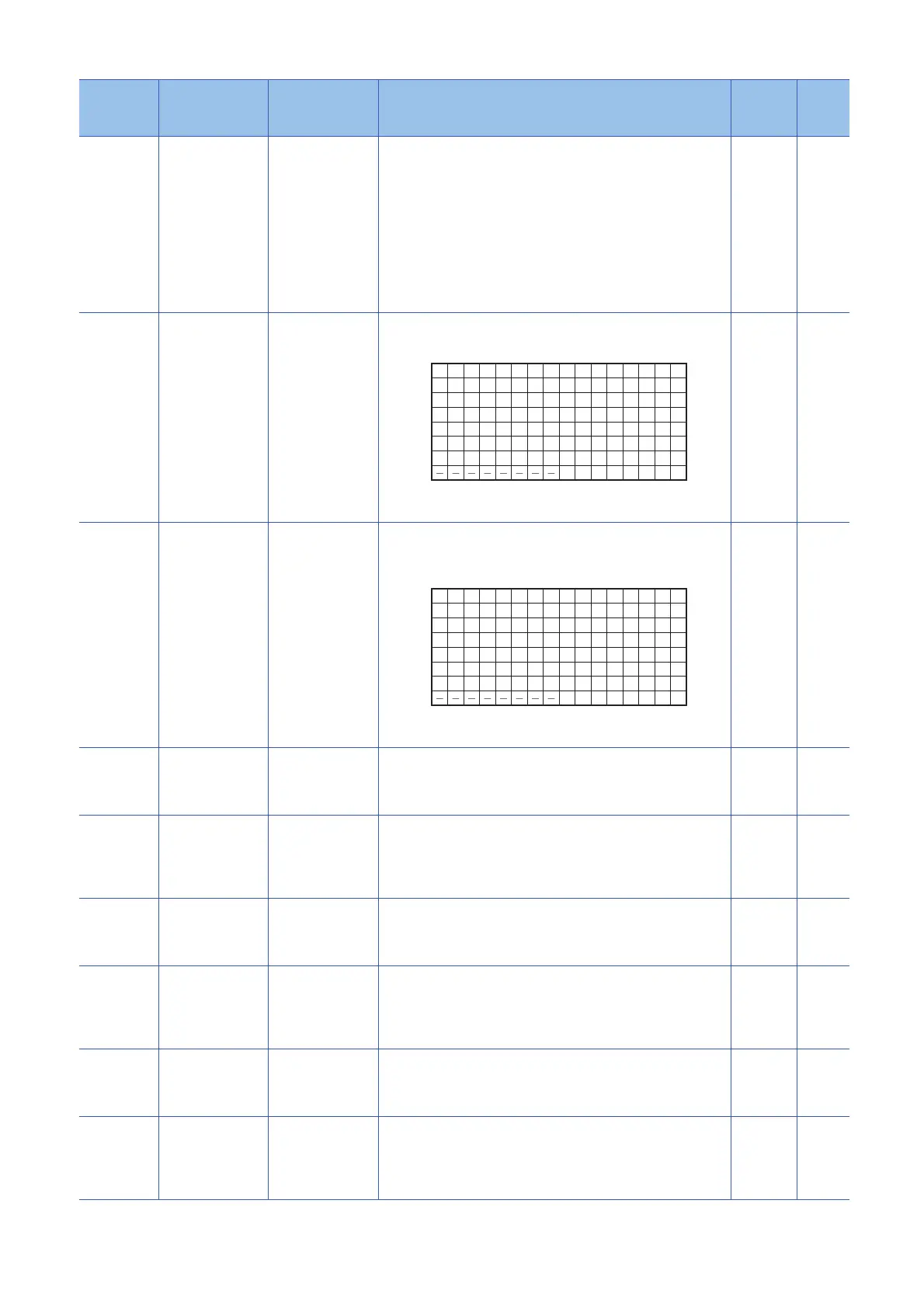
SA\SD1232
to
SA\SD1239
Interlock status of
each safety
connection (1st
module)
0: Not interlocked
1: Interlocked
After safety communication error is detected and the safety connection
is interlocked, the bit corresponding to the safety connection turns on.
1 to 120: Safety connection number
: Fixed to 0
S (Status
change)
RnPSF
RnSF
SA\SD1240
to
SA\SD1247
Interlock release
request for each
safety connection
(1st module)
0: Do not release
the interlock.
1: Release the
interlock.
Turn off and on the bit corresponding to the safety connection to
release the interlock. (The bit does not automatically turn off after
execution is complete.)
*1
1 to 120: Safety connection number
: Fixed to 0
U
(Request)
RnPSF
RnSF
SA\SD1248
to
SA\SD1255
Interlock status of
each safety
connection (2nd
module)
0: Not interlocked
1: Interlocked
After safety communication error is detected and the safety connection
is interlocked, the bit corresponding to the safety connection turns on.
The bit arrangement of the safety connection number is the same as
that of the 1st module. (Note that the SA\SD numbers differ.)
S (Status
change)
RnPSF
RnSF
SA\SD1256
to
SA\SD1263
Interlock release
request for each
safety connection
(2nd module)
0: Do not release
the interlock.
1: Release the
interlock.
Turn off and on the bit corresponding to the safety connection to
release the interlock. (The bit does not automatically turn off after
execution is complete.)
*1
The bit arrangement of the safety connection number is the same as
that of the 1st module. (Note that the SA\SD numbers differ.)
U
(Request)
RnPSF
RnSF
SA\SD1264
to
SA\SD1271
Interlock status of
each safety
connection (3rd
module)
0: Not interlocked
1: Interlocked
After safety communication error is detected and the safety connection
is interlocked, the bit corresponding to the safety connection turns on.
The bit arrangement of the safety connection number is the same as
that of the 1st module. (Note that the SA\SD numbers differ.)
S (Status
change)
RnPSF
RnSF
SA\SD1272
to
SA\SD1279
Interlock release
request for each
safety connection
(3rd module)
0: Do not release
the interlock.
1: Release the
interlock.
Turn off and on the bit corresponding to the safety connection to
release the interlock. (The bit does not automatically turn off after
execution is complete.)
*1
The bit arrangement of the safety connection number is the same as
that of the 1st module. (Note that the SA\SD numbers differ.)
U
(Request)
RnPSF
RnSF
SA\SD1280
to
SA\SD1287
Interlock status of
each safety
connection (4th
module)
0: Not interlocked
1: Interlocked
After safety communication error is detected and the safety connection
is interlocked, the bit corresponding to the safety connection turns on.
The bit arrangement of the safety connection number is the same as
that of the 1st module. (Note that the SA\SD numbers differ.)
S (Status
change)
RnPSF
RnSF
SA\SD1288
to
SA\SD1295
Interlock release
request for each
safety connection
(4th module)
0: Do not release
the interlock.
1: Release the
interlock.
Turn off and on the bit corresponding to the safety connection to
release the interlock. (The bit does not automatically turn off after
execution is complete.)
*1
The bit arrangement of the safety connection number is the same as
that of the 1st module. (Note that the SA\SD numbers differ.)
U
(Request)
RnPSF
RnSF
No. Name Data stored Details Set by
(setting
timing)
CPU
16 15 14 13 12 11 10 9 8 7 6 5 4 3 2 1
b15 b14 b13 b12 b11 b10 b9 b8 b7 b6 b5 b4 b3 b2 b1 b0
32 31 30 29 28 27 26 25 24 23 22 21 20 19 18 17
48 47 46 45 44 43 42 41 40 39 38 37 36 35 34 33
64 63 62 61 60 59 58 57 56 55 54 53 52 51 50 49
80 79 78 77 76 75 74 73 72 71 70 69 68 67 66 65
96 95 94 93 92 91 90 89 88 87 86 85 84 83 82 81
112 111 110 109 108 107 106 105 104 103 102 101 100 99 98 97
120 119 118 117 116 115 114 113
SA\SD1232
SA\SD1233
SA\SD1234
SA\SD1235
SA\SD1236
SA\SD1237
SA\SD1238
SA\SD1239
16 15 14 13 12 11 10 9 8 7 6 5 4 3 2 1
b15 b14 b13 b12 b11 b10 b9 b8 b7 b6 b5 b4 b3 b2 b1 b0
32 31 30 29 28 27 26 25 24 23 22 21 20 19 18 17
48 47 46 45 44 43 42 41 40 39 38 37 36 35 34 33
64 63 62 61 60 59 58 57 56 55 54 53 52 51 50 49
80 79 78 77 76 75 74 73 72 71 70 69 68 67 66 65
96 95 94 93 92 91 90 89 88 87 86 85 84 83 82 81
112 111 110 109 108 107 106 105 104 103 102 101 100 99 98 97
120 119 118 117 116 115 114 113
SA\SD1240
SA\SD1241
SA\SD1242
SA\SD1243
SA\SD1244
SA\SD1245
SA\SD1246
SA\SD1247

 Loading...

