APPX
Appendix 9 Processing Time
927
A
■Waiting time for completion of the previous tracking data reflection
The following describes the waiting time (Twr) for completion of the previous tracking data reflection in the CPU module of the
control system.
Twr = 1 + Tdrm - Toth [ms]
• Tdrm: Maximum time taken for reflection of tracking data in the CPU module of the standby system
• Toth: Scan time excluding Ts (Increase in the scan time) in the CPU module of the control system
Tdrm is determined as follows.
• When no extended SRAM cassette is inserted: 1 + (No. of tracking blocks 0.3) + (Total size of tracking data [word] 45.0)
10
-6
• When an extended SRAM cassette is inserted: 1 + (No. of tracking blocks 0.3) + (Total size of tracking data [word]
106.0) 10
-6
If Tdrm - Toth is smaller than 0, Twr is handled as 1.
Twr is not generated in the first scan in which the tracking transfer is started.
■Tracking data send time
The following describes the tracking data send time (Tst) in the CPU module of the control system. The calculation method
differs depending on whether an extended SRAM cassette is inserted or not.
• D1: Size [word] of tracking data in the system data, signal flow memory, and refresh data register (RD)
• D2: Size [word] of tracking data of global devices, local devices, global labels, and local labels
• D3: Number of tracking transfer settings of global devices
• D4: Size [word] of tracking data in the system data, signal flow memory (standard/safety), and refresh data register (RD)
• D5: Size [word] of tracking data of global devices (standard/safety), local devices (standard/safety), global labels (standard/
safety), local labels (standard/safety), and standard/safety shared labels
• D6: Number of tracking transfer settings of global devices (standard)
• D7: Total size [word] of tracking data in the system data (safety)
*1
, signal flow memory (safety), local devices (safety),
global labels (safety), local labels (safety), global devices (safety), and standard/safety shared labels
*1 For the size of the system data (safety), refer to the value for D4 "Variable depending on safety communication status" in "System
data".
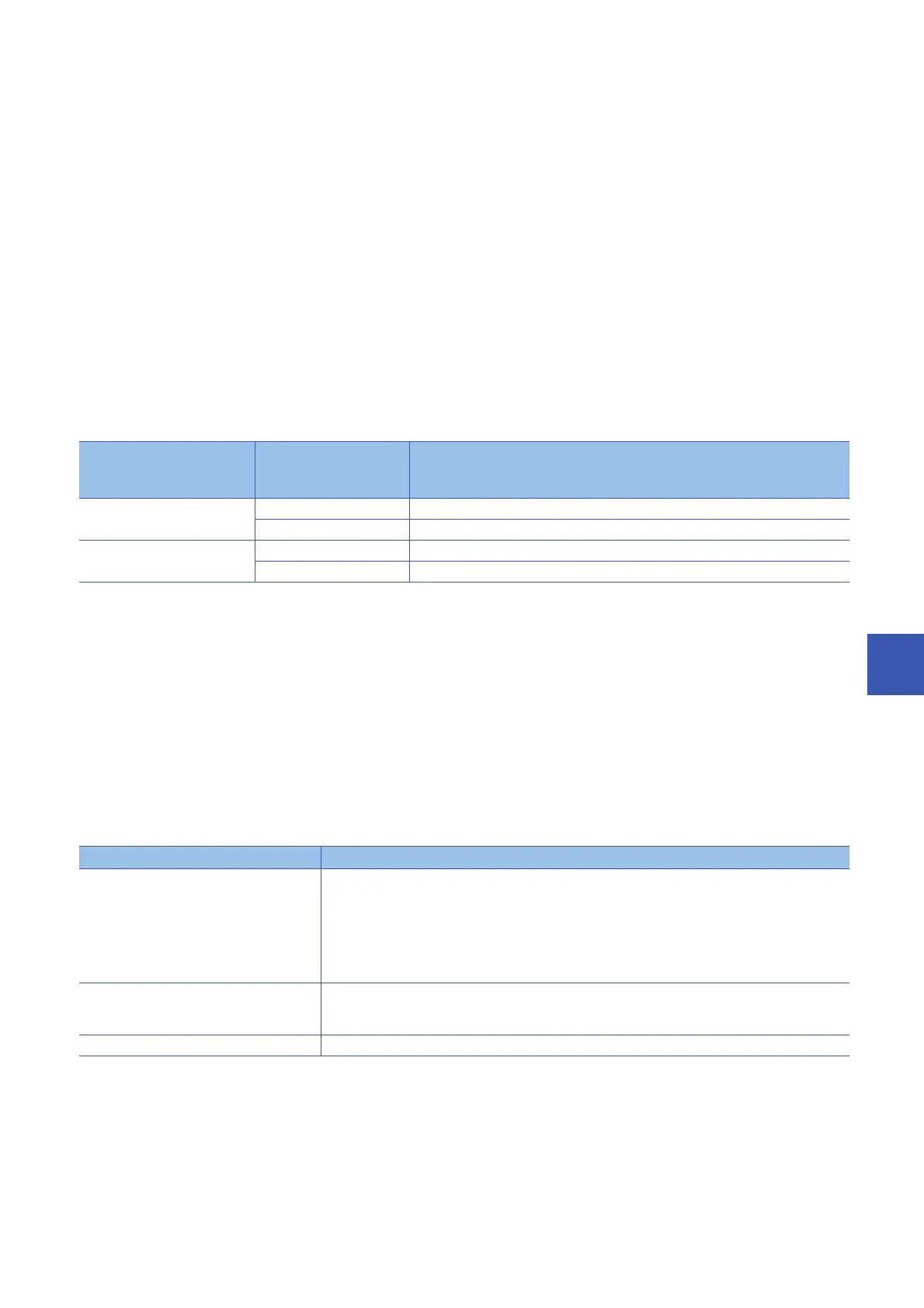
D1 is determined as follows.
CPU module Extended SRAM
cassette inserting
status
Tracking data send time
Process CPU (redundant mode) Not inserted 0.5 + (26.7 10
-6
) D1 + (43.5 10
-6
) D2 + (1.5 10
-3
) D3[ms]
Inserted 0.5 + (26.7 10
-6
) D1 + (113.5 10
-6
) D2 + (1.5 10
-3
) D3[ms]
SIL2 Process CPU Not inserted 0.58 + (26.7 10
-6
) D4 + (43.5 10
-6
) D5 + (1.5 10
-3
) D6 + (66.0 10
-6
) D7[ms]
Inserted 0.58 + (26.7 10
-6
) D4 + (113.5 10
-6
) D5 + (1.5 10
-3
) D6 + (66.0 10
-6
) D7[ms]
Item Size
System data ■Fixed data
8217
■PID control instruction information
782 (0 (when not used))
■Data that varies depending on the tracking device/label setting
16 (No. of tracking settings of T, ST, C, and LC) + 8 (No. of global device tracking settings of other
devices)
Signal flow memory (Total number of steps of control system execution programs, or total number of steps of rising/falling
instruction in an FB)/16
(The digit after the decimal point is round up.)
Refresh data register (RD) Follows the tracking transfer settings. ( Page 460 Tracking transfer setting)

 Loading...

