REAR AXLE – Hydraulic Unit <Vehicles with AYC>
27-50
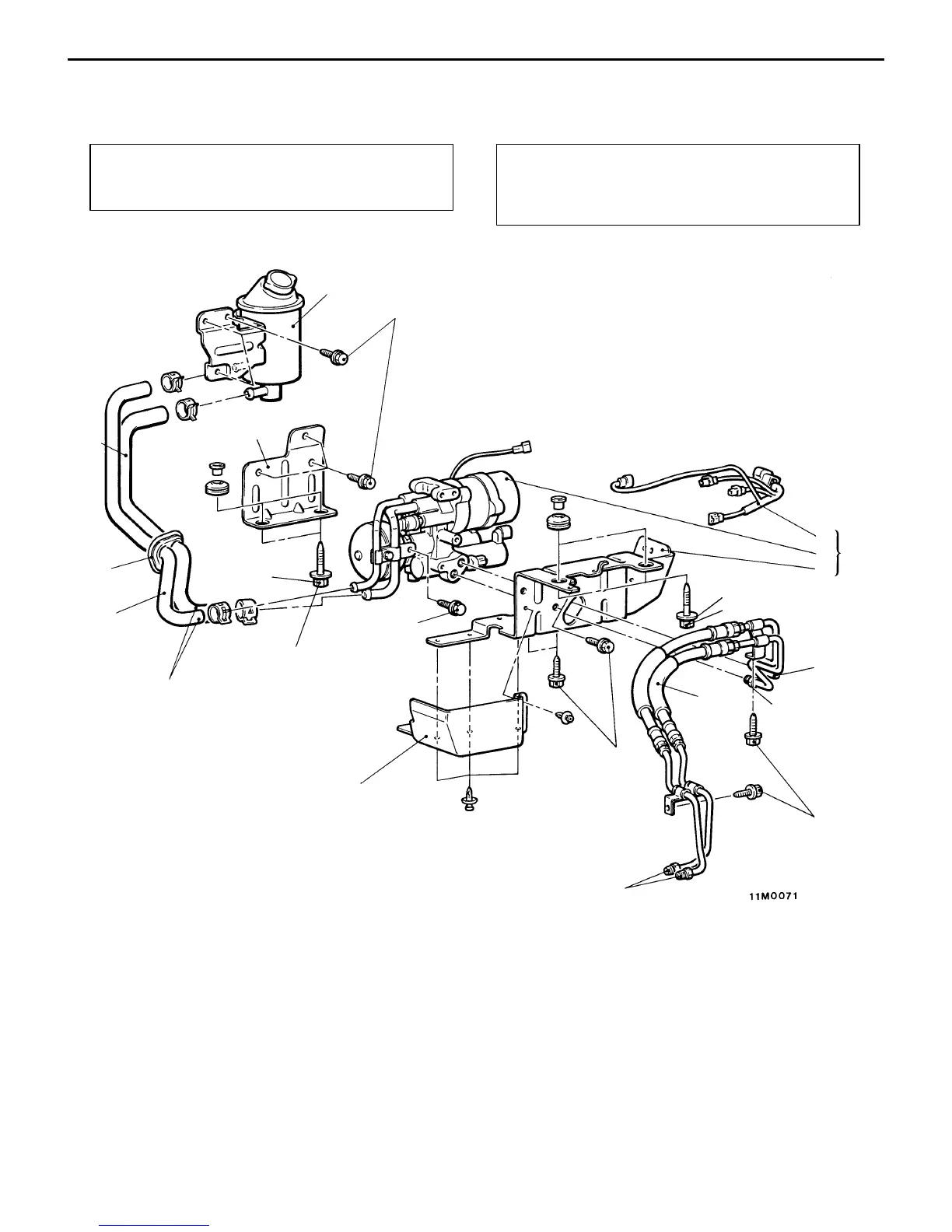
HYDRAULIC UNIT <VEHICLES WITH AYC>
REMOVAL AND INSTALLATION
Pre-removal Operation
(1) Trunk Side Trim Removal
(2) Hydraulic Piping Fluid Draining
Post-installation Operation
(1) Hydraulic Piping Fluid Filling and Bleeding
(Refer to P.27-29.)
(2) Trunk Side Trim Installation
1
2
3
4
5
6
7
8
9
10
11
12
13
14
Unit: Nm {kgf@m}
12 {1.2}
4
12 {1.2}
18 {1.8}
12 {1.2}
12 {1.2}
18 {1.8}
34 {3.5}
34 {3.5}
Removal steps
1. Dust guard
2. Suction hose and return hose con-
nection
3. Hydraulic unit hose assembly con-
nection
4. Hydraulic unit and bracket assem-
bly mounting bolt
"CA 5. Hydraulic unit and bracket assem-
bly
6. Hydraulic unit
7. Hydraulic unit bracket
8. AYC harness
9. Hydraulic unit bracket
10. Hydraulic unit hose assembly
"BA 11. Return hose
"BA 12. Suction hose
"AA 13. Grommet
14. Oil reservoir
Caution
(1) When connecting the return hose and suction
hose, do not apply lubricant.
(2) No foreign matter should be allowed in the
hydraulic piping and joints.