ABS – Wheel Speed Sensor
35B-18
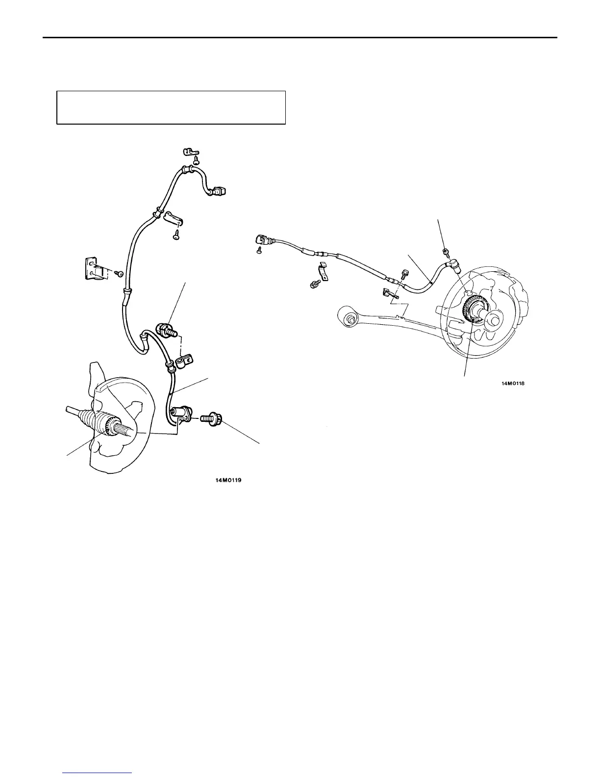
WHEEL SPEED SENSOR
REMOVAL AND INSTALLATION
Post-installation Operation
D Wheel Speed Sensor Output Voltage Measurement
1
2
3
4
Unit: Nm {kgf@m}
25 {2.6}
25 {2.6}
25 {2.6}
Front speed sensor removal steps
D Splash shield
1. Front speed sensor
2. Front rotor (Refer to GROUP 26
DRIVE SHAFT.)
Rear speed sensor removal steps
3. Rear speed sensor
4. Rear rotor (Refer to GROUP 27
REAR AXLE HUB.)
NOTE
The front rotor and rear rotor are integrated with the drive
shaft and thus nonmaintainable.
Caution
When removing and installing the speed sensor and
rotor, use care not to allow the surfaces of the ball
piece and rotor at the end of the speed sensor to
be hit against a metal or other object, damaging
it.