REAR AXLE – Differential Carrier <EVOLUTION-IV, EVOLUTION-V GSR>
27-39
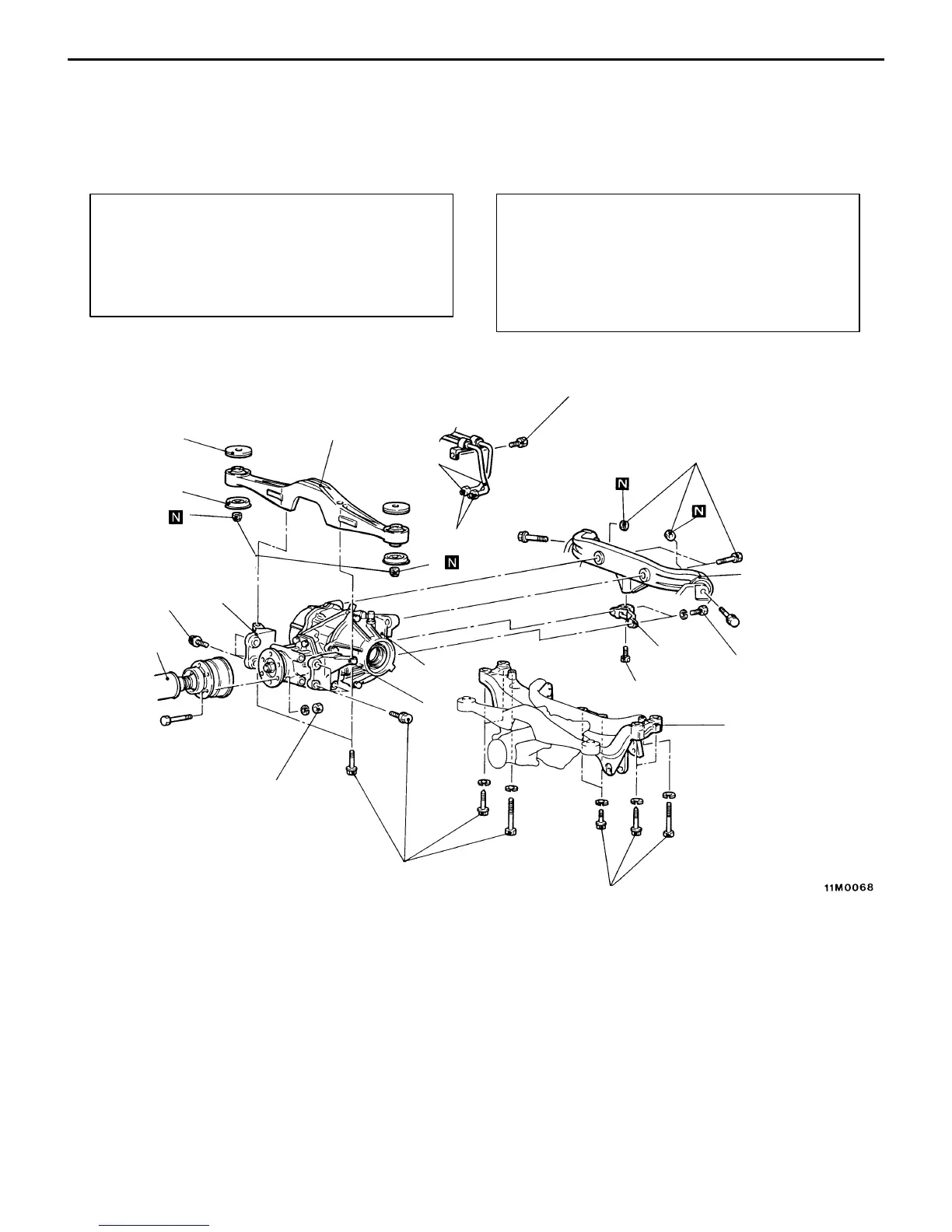
DIFFERENTIAL CARRIER
<EVOLUTION-IV, EVOLUTION-V GSR>
REMOVAL AND INSTALLATION
<Vehicles with AYC>
Pre-removal Operation
(1) Hydraulic Piping Fluid Draining
(2) Gear Oil Draining (Refer to P.27-28.)
(3) Lower Arm Assembly Removal
(Refer to GROUP 34.)
(4) Rear Stabilizer Removal (Refer to GROUP 34.)
(5) Drive Shaft Removal (Refer to P.27-36.)
Post-installation Operation
(1) Drive Shaft Installation (Refer to P.27-36.)
(2) Rear Stabilizer Installation (Refer to GROUP 34.)
(3) Lower Arm Assembly Installation
(Refer to GROUP 35.)
(4) Gear Oil Filling (Refer to P.27-28.)
(5) Hydraulic Piping Fluid Filling and Bleeding
(Refer to P.27-29.)
1
2
3
4
5
6
7
8
9
10
11
Unit: Nm {kgf@m}
12 {1.2}
29 – 34
{3.0 – 3.5}
88 {9.0}
88 {9.0}
88 {9.0}
44 {4.5}
88 {9.0}
34 {3.5}
3
108 – 127 {11.0 – 13.0}
9
88 {9.0}
Removal steps
1. Hydraulic unit hose assembly con-
nection
"BA 2. Propeller shaft connection
3. Differential support member mount-
ing bolt
AA""AA 4. Rear crossmember and differential
carrier assembly
5. Differential support member
6. Upper stopper
7. Lower stopper
8. Differential support arm
9. Differential mount bracket
10. Differential mount bracket
11. Differential carrier