BASIC BRAKE SYSTEM – Brake Pedal
35A-4
BRAKE PEDAL <L.H. DRIVE VEHICLES>
REMOVAL AND INSTALLATION
Pre-removal Operation
D Instrument Under Cover Removal
D Steering Column Assembly Removal
(Refer to GROUP 37A – Steering Wheel and Shaft.)
D Accelerator Pedal Removal
Post-installation Operation
D Accelerator Pedal Installation
D Steering Column Assembly Installation
(Refer to GROUP 37A – Steering Wheel and Shaft.)
D Instrument Under Cover Installation
D Brake Pedal Adjustment (Refer to P.35A-2.)
29 Nm
12 Nm
14 Nm
1
2
3
4
5
6
7
8
13 Nm
11
9
10
8
9
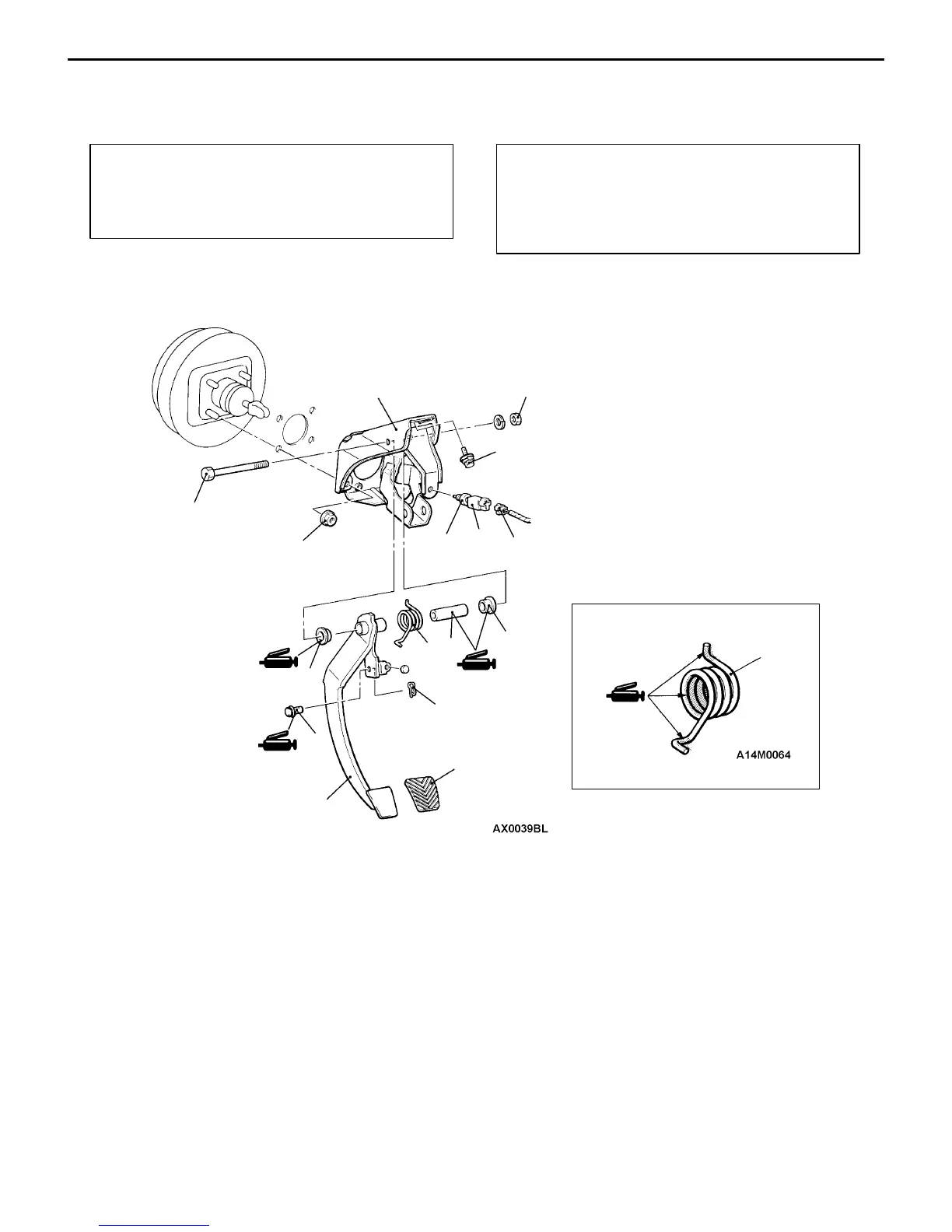
Removal steps
1. Stop lamp switch connector
2. Stop lamp switch
3. Snap pin
4. Clevis pin
5. Brake pedal shaft bolt
6. Brake pedal
7. Brake pedal pad
8. Brake pedal return spring
9. Bushing
10. Pipe
11. Pedal support member

 Loading...