BASIC BRAKE SYSTEM – Master Cylinder and Brake Booster
35A-5
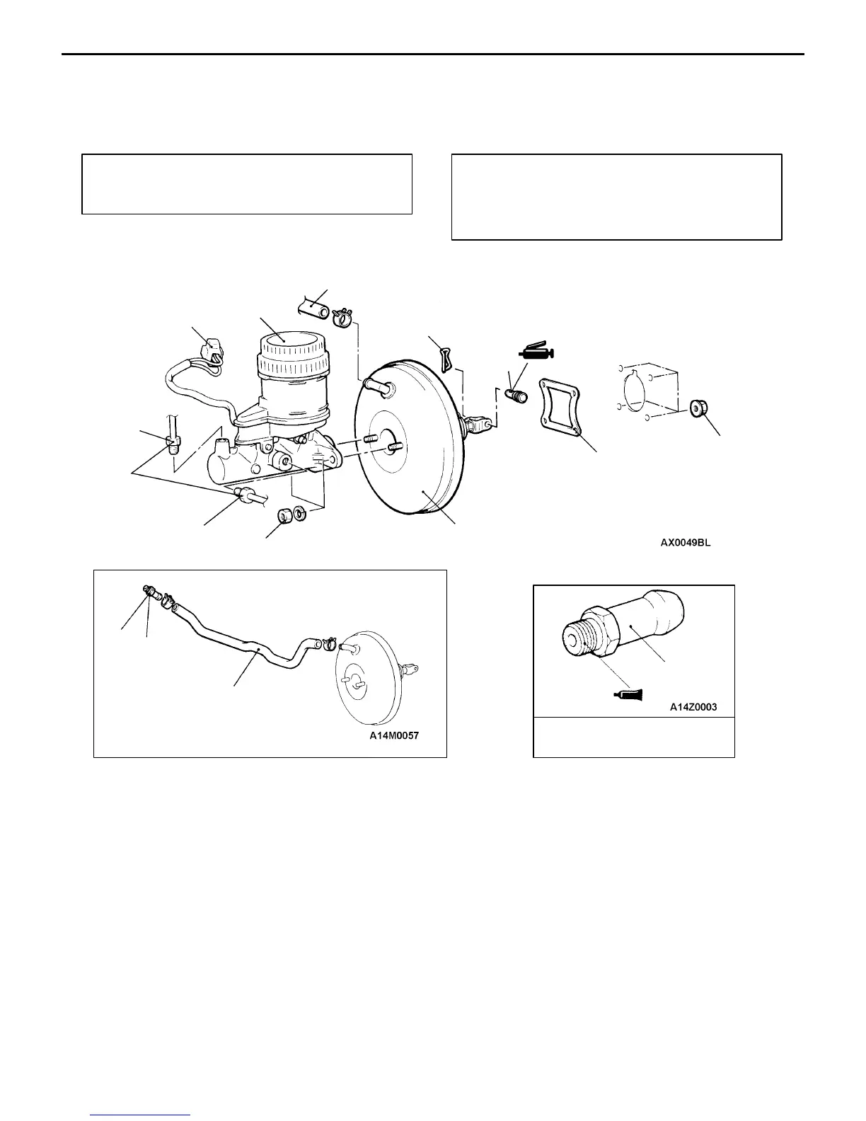
MASTER CYLINDER AND BRAKE BOOSTER
<L.H. DRIVE VEHICLES>
REMOVAL AND INSTALLATION
Pre-removal Operation
D Brake Fluid Draining
D Air Intake Hose Removal
Post-installation Operation
D Brake Fluid Supplying
D Brake Line Bleeding
D Brake Pedal Adjustment (Refer to P.35A-2.)
D Air Intake Hose Installation
15–18 Nm
15 Nm
Sealant: 3M ATD Part No.
8661 or equivalent
6
7
3
1
4
2
8
5
4
14 Nm
5
9
1
10 Nm
Removal steps
1. Brake pipe connection
2. Brake fluid level sensor connector
3. Master cylinder assembly
"BADClearance adjustment between brake
booster push rod and primary piston
"AA 4. Vacuum hose
(With built-in check valve)
5. Fitting
6. Snap pin
7. Clevis pin assembly
8. Brake booster
9. Sealer