ABS – Troubleshooting
35B-16
Terminal
No.
NormallyCheck requirementCheck item
44 Wheel speed (RR) output Vehicle stationary 1 V or less
Moving forward slowly 0 – 5 V
48 Valve relay monitor input Ignition switch: ON (after initial check) Battery voltage
49 Motor relay monitor output Ignition switch:
When motor is energized 0 V
When motor is deenergized Battery voltage
50 ABS warning lamp output Ignition switch:
When lamp is off Battery voltage
When lamp is on 0 V
51 Solenoid valve IN (RL) output Ignition switch: ON (after initial check) Battery voltage
52 Solenoid valve IN (FR) output Ignition switch: ON (after initial check) Battery voltage
5-2 LISTING OF RESISTANCE AND CONTINUITY ACROSS CONNECTOR TERMINALS ON
HARNESS SIDE
(1) Measure the resistance and check for continuity with the ignition switch in the ”OFF” position and
ABS-ECU connector disconnected.
(2) Measure the resistance and check for continuity across terminals listed below.
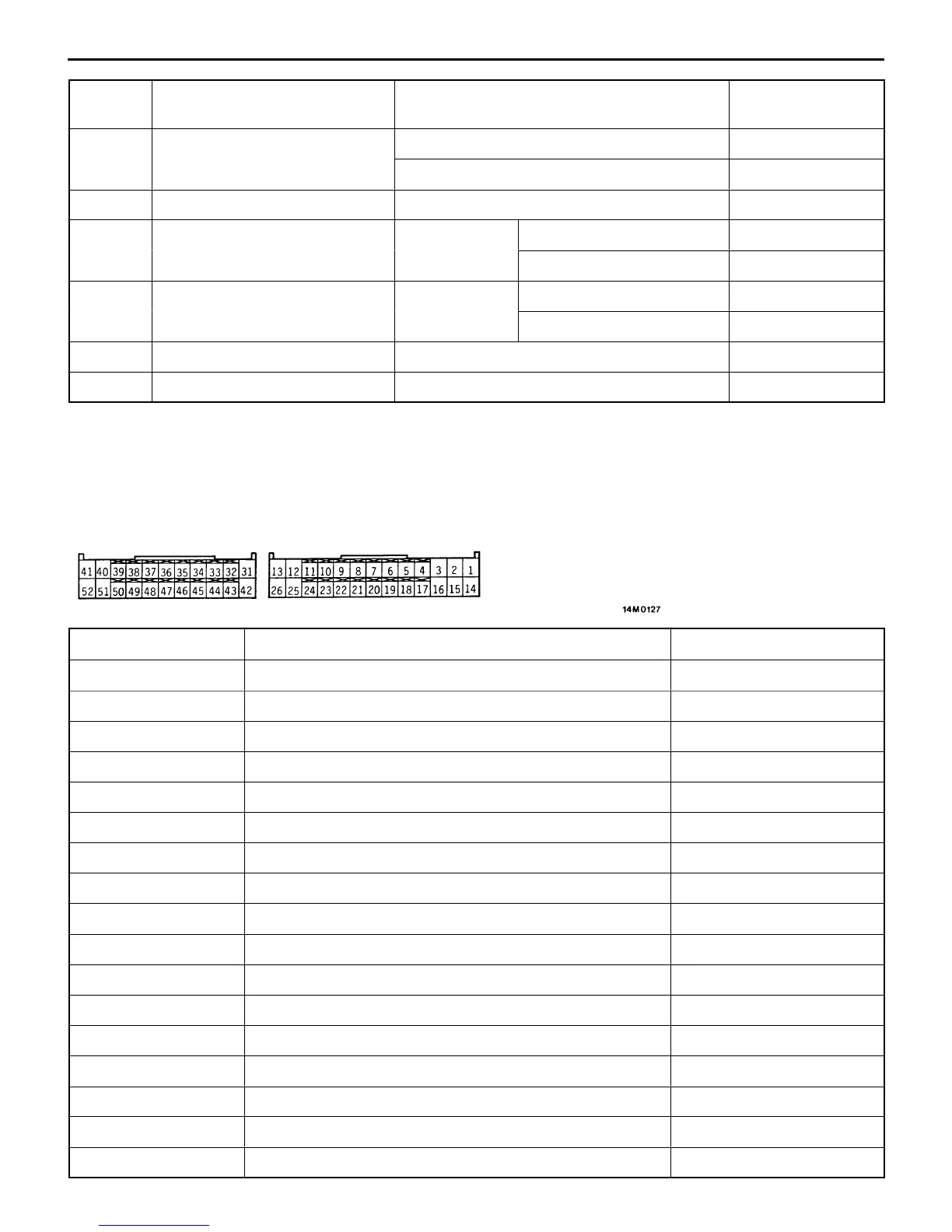
(3) Fig. below shows the arrangement of terminals.
Terminal No. Signal name Normally
1 – body ground Solenoid valve OUT (FL) output 4.04 – 4.54 Ω
2 – body ground Solenoid valve OUT (RR) output 4.04 – 4.54 Ω
3 – body ground Solenoid valve IN (RR) output 8.04 – 9.04 Ω
7 – 20 Wheel speed sensor (FL) input 1.4 – 1.8 kΩ
8 – 21 Wheel speed sensor (RR) input 1.4 – 1.8 kΩ
9 – 22 Wheel speed sensor (RL) input 1.4 – 1.8 kΩ
10 – 23 Wheel speed sensor (FR) input 1.4 – 1.8 kΩ
14 – body ground Solenoid valve IN (FL) output 8.04 – 9.04 Ω
15 – body ground Ground Conducting
25 – body ground Ground Conducting
40 – body ground Solenoid valve OUT (RL) output 4.04 – 4.54 Ω
41 – body ground Solenoid valve OUT (FR) output 4.04 – 4.54 Ω
42 – body ground Ground Conducting
48 – body ground Valve relay monitor input Conducting
49 – body ground Motor relay monitor input Conducting
51 – body ground Solenoid valve IN (RL) output 8.04 – 9.04 Ω
52 – body ground Solenoid valve IN (FR) output 8.04 – 9.04 Ω