CHASSIS ELECTRICAL – Combination Meters
54-26
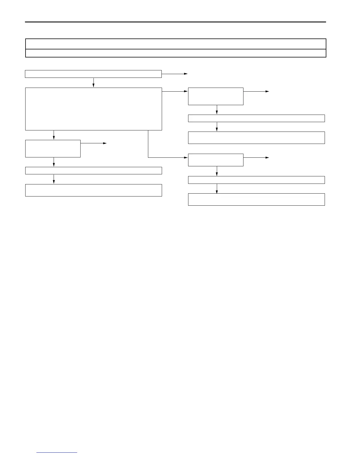
Inspection Procedure 3
Vehicle speed sensor circuit system inspection
Signals from the vehicle speed sensor are utilized both in the speedometer and the engine-ECU.
Vehicle speed sensor inspection (Refer to P.54-27.)
NG
Replace
OK
Disconnect the vehicle speed sensor connector A-19 and measure
at the harness side.
1. Voltage between the terminal No.1 and earth
OK: System voltage
2. Continuity between terminal No.2 and earth
OK: Continuity
3. Voltage between the terminal No.3 and earth
OK: 4.5 V or more
1. NG
Check the following
connectors. A-19, B-64
NG
Repair
OK
Check trouble symptom.
NG
Check the harness wire between the vehicle speed sensor and
multi-purpose fuse 4, and repair if necessary.
3. NG
Check the following
connectors. A-19, B-64,
B-08
NG
Repair
2. NG
Check the following
connector. A-19
NG
Repair
OK
Check trouble symptom.
NG
Check the harness between the vehicle speed sensor and combina-
tion meter, and repair if necessary.
OK
Check trouble symptom.
NG
Check the harness wire between the vehicle speed sensor and
body earth, and repair if necessary.
NOTE
If the trouble symptom still persists even after the above procedures are performed, check the vehicle
speed senosor output signal side circuit (harness, speedometer and engine ECU) for short-circuit.