CHASSIS ELECTRICAL – Combination MetersCHASSIS ELECTRICAL – Combination MetersCHASSIS ELECTRICAL – Combination Meters
54-31
INSPECTION
FUEL GAUGE RESISTANCE CHECK
1. Remove the power supply tightening screw.
2. Use a circuit tester to measure the resistance value
between the terminals.
Standard value: Unit: Ω
Measurement terminal Resistance value
Power supply – Earth 192±19.2
Power supply – Fuel gauge 89±8.9
Fuel gauge – Earth 103±10.3
Caution
When inserting the testing probe into the power supply
terminal, be careful not to touch the printed board.
ENGINE COOLANT TEMPERATURE GAUGE
RESISTANCE CHECK
1. Remove the power supply tightening screw.
2. Use a circuit tester to measure the resistance value
between the terminals.
Standard value: Unit: Ω
Measurement terminal Resistance value
Power supply – Earth 187±18.7
Power supply – Engine coolant
temperature gauge
90±4.5
Engine coolant temperature
gauge – Earth
247±24.7
Caution
When inserting the testing probe into the power supply
terminal, be careful not to touch the printed board.
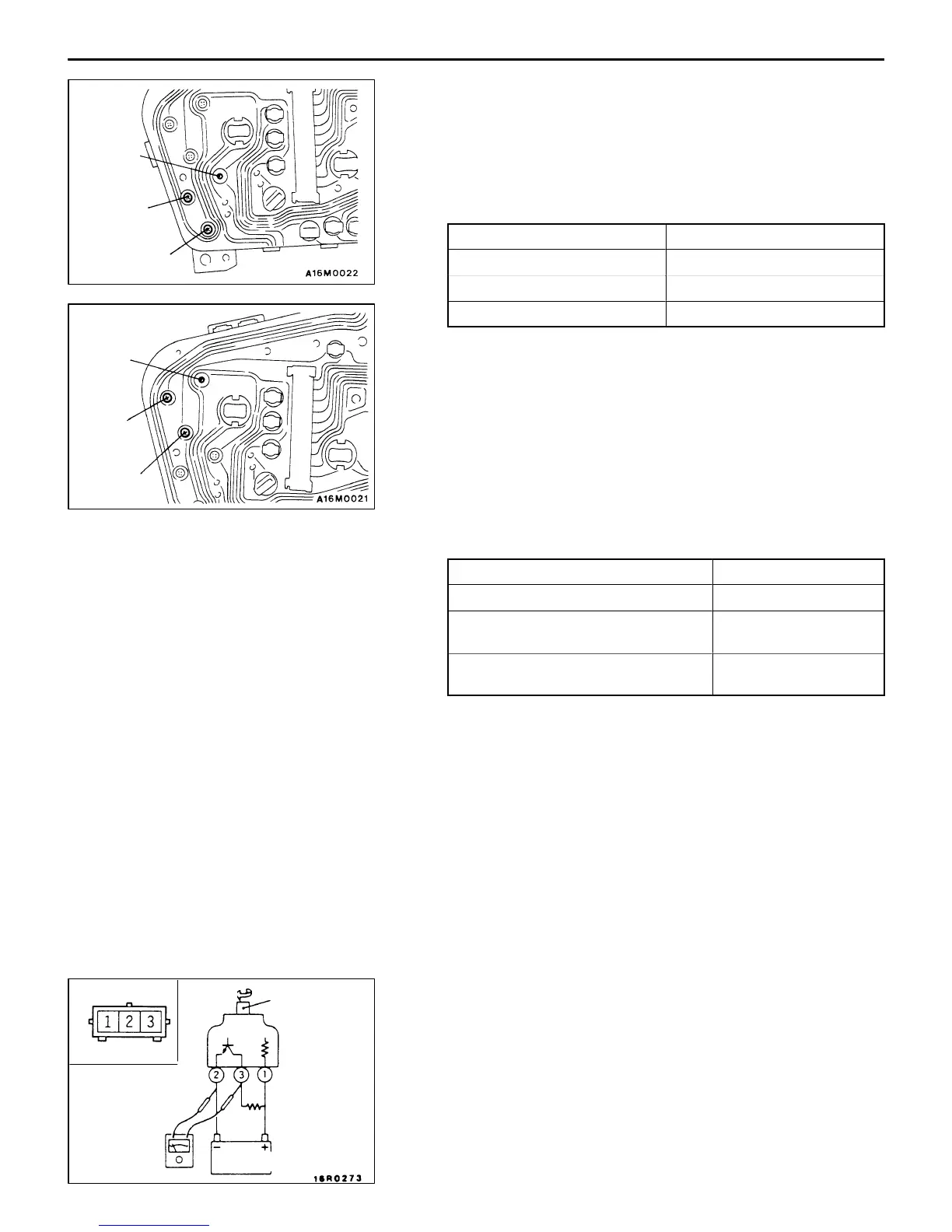
VEHICLE SPEED SENSOR CHECK
1. Connect a 3 – 10 kΩ resistance as shown in the illustration.
2. Turn the shaft of the vehicle speed sensor one turn and
check that voltage changes are caused when measured
between terminals 2 and 3 using a circuit tester. (1 turn
= 4 pulses)
Fuel gauge
Power
supply
Earth
Earth
Power
supply
Engine
coolant
temperature
gauge
Turn
Shaft
Circuit tester
Resistance
3 – 10 kΩ
Vehicle
speed
sensor
Terminal No.
16R0273
Battery