MPI – Troubleshooting
13-15
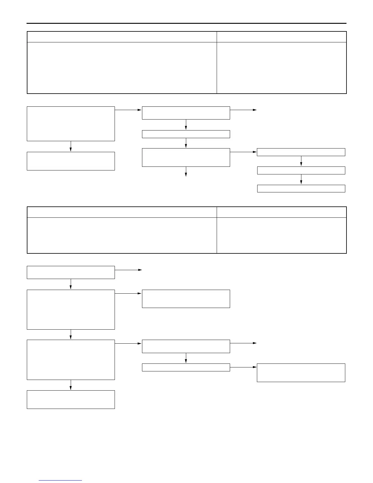
Code No. 31 Detonation sensor system Probable cause
Range of Check
D Ignition switch: ON
D Excluding 60 seconds after the ignition switch is turned to ON or immediately
after the engine starts.
D Engine speed is approx. 5,000 r/min or more
D Set conditions
D The change in the detonation sensor output voltage (detonation sensor peak voltage
at each 1/2 revolution of the crankshaft) is less than 0.06 V for 200 times in
succession.
D Malfunction of the detonation sensor
D Improper connector contact, open or short-circuited
harness wire of the detonation sensor circuit
D Malfunction of the engine-ECU
Measure at the detonation sensor con-
nector A-96.
D Disconnect the connector and
measure at the harness side.
D Continuity between 2 and earth
OK: Continuity
OK
Check the following connector:
B-62
NG
Repair
OK
Check trouble symptom.
NG
Check the harness wire between the
engine-ECU and the detonation sensor
connector.
OK
Replace the detonation sensor.
Check trouble symptom.
NG
Replace the engine-ECU.
NG
Repair
NG
Check the harness wire between the
detonation sensor and earth, and repair
if necessary.
Code No. 41 Injector system Probable cause
Range of Check
D Engine speed is approx. 50–1,000 r/min
D The throttle position sensor output voltage is 1.15 V or less.
D Actuator test by MUT-II is not carried out.
Set conditions
D Surge voltage of injector coil is not detected for 4 seconds.
D Malfunction of the injector
D Improper connector contact, open or short-circuited
harness wire of the injector circuit
D Malfunction of the engine-ECU
OK
Check trouble symptom.
NG
Check the harness wire between the
resistor and the injector connector, and
repair if necessary.
Check the injector control circuit.
(Refer to P.13-55, INSPECTION PRO-
CEDURE 50.)
OK
OK
Measure at the injector connectors
A-53, A-54, A-55, A-56
D Disconnect the connector, and
measure at the harness side.
D Voltage between 1 and earth
(Ignition switch: ON)
OK: System voltage
NG
Check the following connector:
A-125
NG
Repair
OK
Measure at the resistor connector
A-125.
D Disconnect the connector, and
measure at the harness side.
D Voltage between 3 and earth
(Ignition switch: ON)
OK: System voltage
NG
Check the harness wire between the
control relay and the resistor connector,
and repair if necessary.
Check the injector. (Refer to P.13-34.)*
Check the resistor. (Refer to P.13-34.)*
NG
Replace
NOTE
*: Refer to Workshop Manual for LANCER EVOLUTION-IV and EVOLUTION-V (Pub. No. S9806CNCP9).