FRONT AXLE – General / Axle Hub and Knuckle <EVOLUTION-VI>
26-1
GROUP 26
FRONT AXLE
GENERAL
OUTLINE OF CHANGE
D The installation method of the ball joint between the knuckle and the lower arm has been changed,
and accordingly the removal and installation procedures of the axle hub and the knuckle have been
revised. <EVOLUTION-VI>
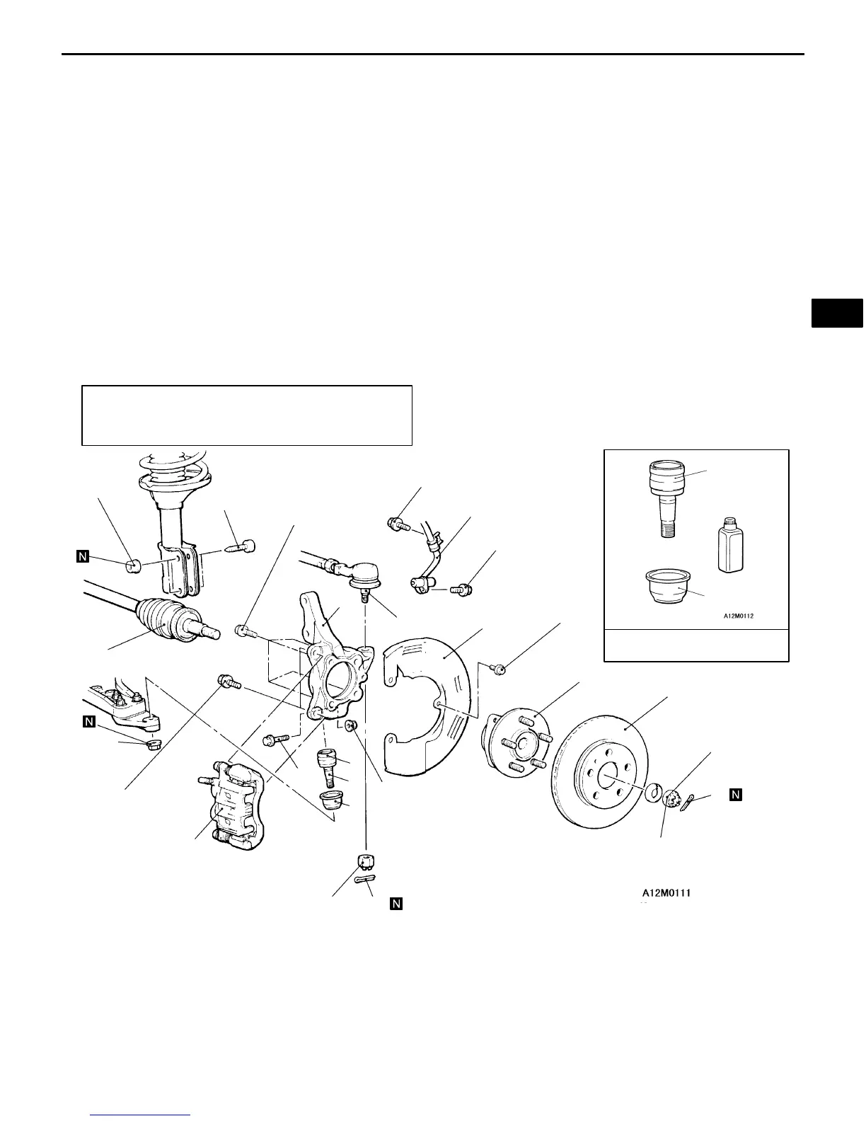
AXLE HUB AND KNUCKLE <EVOLUTION-VI>
REMOVAL AND INSTALLATION
Caution
(1) For vehicles with AYC, be careful when handling the pole piece at the tip of the speed sensor so as
not to damage it by striking against other parts.
(2) For vehicles with AYC, be careful not to damage the rotors installed to B.J. outer race during removal
and installation of the drive shaft.
Post-installation Operation
D Check the Dust Cover for Cracks or Damage by
Pushing it with Finger.
1
2
3
4
5
6
7
8
12
14
15
13
88 Nm
108 – 127 Nm
90 – 110 Nm
15 – 33 Nm
177 – 275 Nm
25 Nm
25 Nm
9 Nm
103 Nm
74 –87
Nm
11
9
10
16
10
11
Ball joint kit
Removal steps
1. Front speed sensor<Vehicles with
AYC>
AA" 2. Caliper assembly
3. Brake disc
4. Split pin
AB""AA 5. Drive shaft nut
6. Front hub assembly
7. Dust shield
8. Connection for lower arm ball joint
9. Connection bolt for lower arm joint
10. Lower arm ball joint
11. Dust cover
12. Split pin
AC" 13. Connection for tie rod end
AD" 14. Front drive shaft
15. Front strut mounting bolt
16. Knuckle
NOTE
Follow the conventional procedures for removal
and installation service points.