MPI – Troubleshooting
13-38
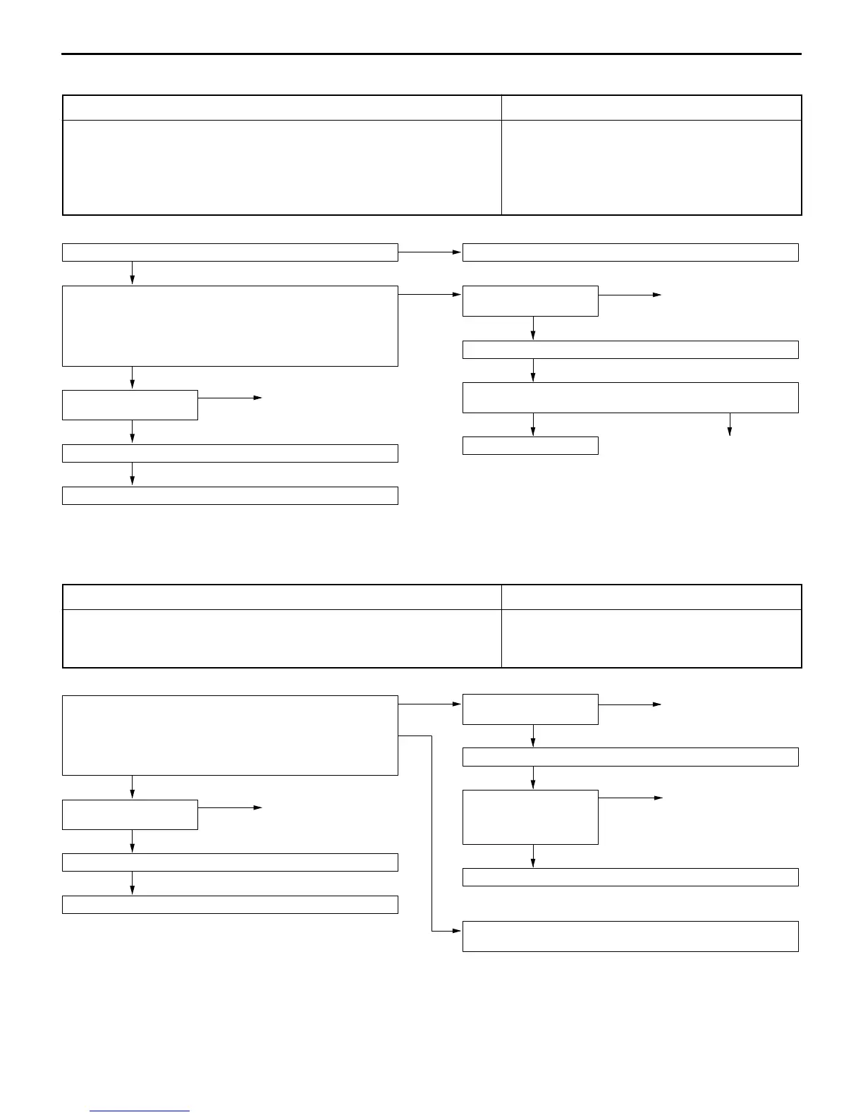
INSPECTION PROCEDURE 26
Idle position switch system
Probable cause
The idle position switch inputs the condition of the accelerator pedal, i.e. whether
it is depressed or released (HIGH/LOW), to the engine-ECU.
The engine-ECU controls the idle speed control servo based on this input.
D Maladjustment of the accelerator cable
D Maladjustment of the fixed SAS
D Maladjustment of the idle position switch and throttle
position sensor
D Improper connector contact, open or short-circuited
harness wire
D Malfunction of the engine-ECU
Check the idle position switch. (Refer to P.13-30.)*
NG
Replace the throttle position sensor.
OK
Measure at the throttle position sensor connector A-16.
D Disconnect the connector, and measure at the harness side.
D Voltage between 3 and earth (Ignition switch: ON)
OK: 4 V or higher
D Continuity between 4 and earth
OK: Continuity
NG
Check the following
connector: B-62
NG
Repair
OK
Check trouble symptom.
NG
Check the harness wire between engine-ECU and throttle position
sensor connector.
OK
Replace the engine-ECU.
NG
Repair
OK
Check the following
connector: A-16
NG
Repair
OK
Check trouble symptom.
NG
Replace the engine-ECU.
NOTE
*: Refer to Workshop Manual for LANCER EVOLUTION-IV and EVOLUTION-V (Pub. No. S9806CNCP9).
INSPECTION PROCEDURE 27
Ignition switch-ST system
Probable cause
The ignition switch-ST inputs a HIGH signal to the engine-ECU while the engine is
cranking.
The engine-ECU controls fuel injection, etc. during starting based on this input.
D Malfunction of ignition switch
D Improper connector contact, open or short-circuited
harness wire
D Malfunction of the engine-ECU
Measure at the engine-ECU connector B-62.
D Disconnect the connector, and measure at the harness side.
1. Voltage between 71 and earth (Ignition switch: START)
OK: 8V
2. Continuity between 91 and earth
OK: Continuity
1. NG
Check the following
connector: B-64
NG
Repair
OK
Check trouble symptom.
NG
Check harness wire be-
tween the engine-ECU
and ignition switch con-
nector.
NG
Repair
OK
Check the ignition switch.
2. NG
Check the harness wire between engine-ECU connector (terminal
No.91) and earth, and repair if necessary.
OK
Check the following
connector: B-62
NG
Repair
OK
Check trouble symptom.
NG
Replace the engine-ECU.