STEERING – General / Steering Wheel and Shaft
37A-2
GENERAL
OUTLINE OF CHANGE
D The service procedures for left-hand drive vehicles have been established as described below. The
service procedures for components not mentioned below are the same as for the preceding models.
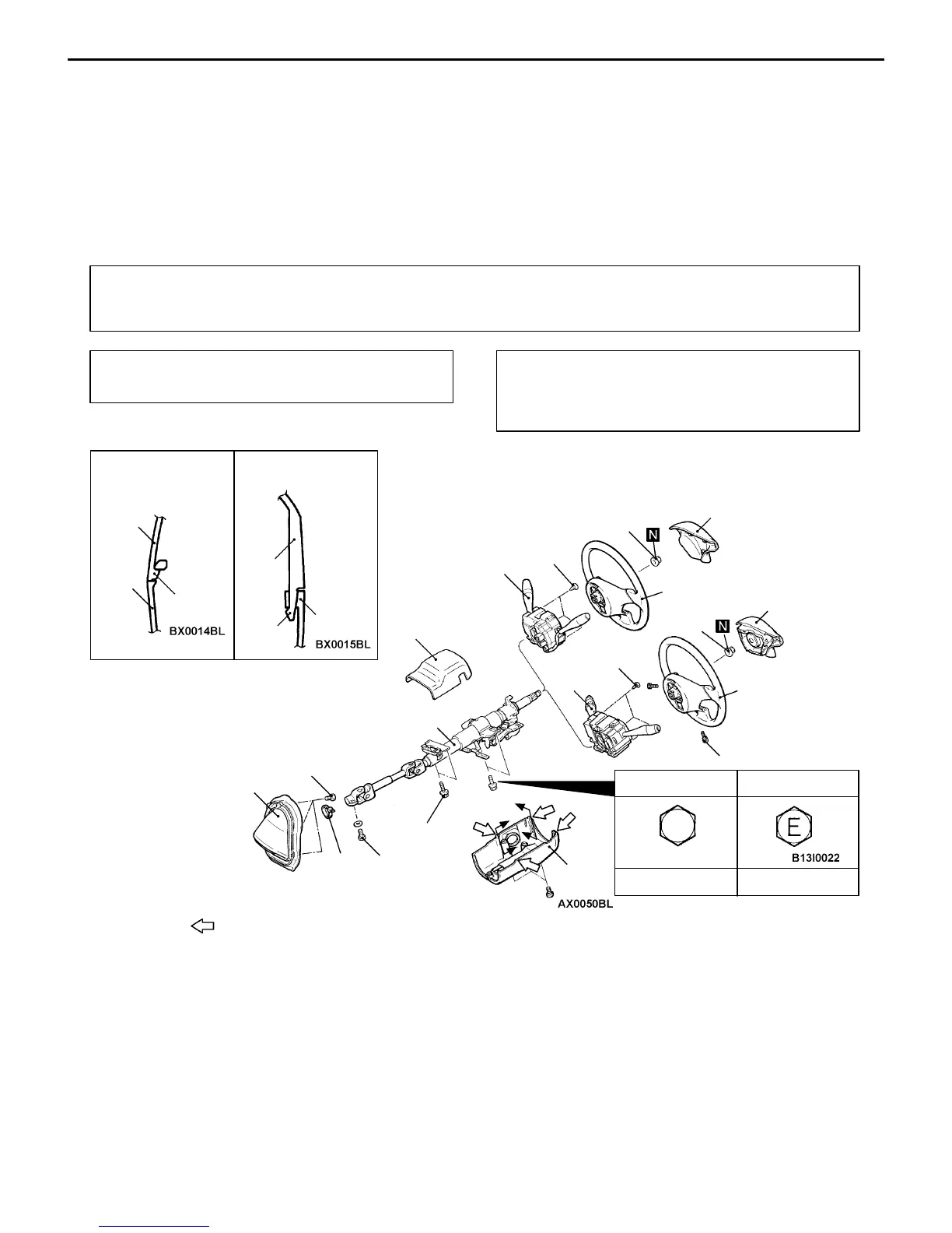
STEERING WHEEL AND SHAFT <L.H. DRIVE VEHICLES>
REMOVAL AND INSTALLATION
CAUTION: SRS
For vehicles with SRS, before removal of air bag module, refer to GROUP 52B – Service Precautions and
Air Bag Module and Clock Spring.
Pre-removal Operation
Instrument Under Cover Removal
Post-installation Operation
D Instrument Under Cover Installation
D Checking Steering Wheel Position with Wheels
Straight Ahead
<Vehicles without SRS>
5 Nm
17 Nm
11 Nm
<Vehicles with SRS>
10
9
8
4
3
1
5
3
2
41 Nm
25 Nm
6
25 Nm
41 Nm
7
9 Nm
Section A – A Section B – B
Claw
: Claw position
A
B
4
5
A
B
11 Nm 21 Nm
Standard bolt Earth bolt
NOTE
4
5
Claw
Removal steps
1. Horn pad <Vehicles without SRS>
2. Air bag module
(Refer to GROUP 52B – Air Bag
Module and Clock Spring.)
AA" 3. Steering wheel
4. Upper column cover
5. Lower column cover
"AA 6. Column switch
<Vehicles without SRS>
"AA 7. Clock spring and column switch
(Refer to GROUP 52B – Air Bag
Module and Clock Spring.)
8. Steering shaft assembly
9. Band
10. Steering cover assembly