BODY – Sunroof
42-12
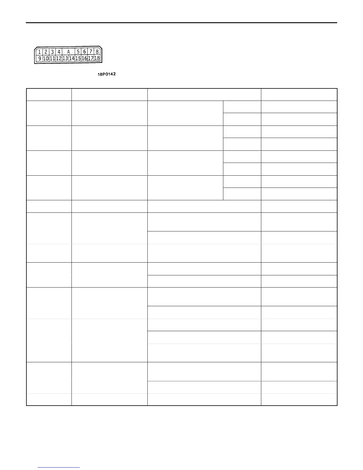
TERMINAL VOLTAGE CHART
Terminal No. Check Item Check Condition Normal Condition
1 Door switch input Driver’s door switch ON 0 V
OFF System voltage
2 Sunroof switch (up) input Sunroof switch
ON 0 V
up pos
on
OFF System voltage
3 Sunroof switch (close or
Sunroof switch (close
position or down position)
ON 0 V
own
npu
pos
on or
own pos
on
OFF System voltage
4 Sunroof switch (open
Sunroof switch
ON 0 V
npu
open pos
on
OFF System voltage
5 ECU power supply Ignition switch: ON System voltage
6 Motor output (When
sunroof is opening)
While sunroof is opening or moving
down
System voltage
Other than the above 0 V
7 Timer operation power
supply
Always System voltage
8 Motor output (When
f
While sunroof is closing or moving up System voltage
sunroo
s c
os
ng
Other than the above 0 V
9 Limit switch 3 input In tilt up condition and fully-open
condition
0 V
Other than the above System voltage
10 Limit switch 1 input In tilt up condition System voltage
In fully-closed and fully-open conditions 0 V
In slide-closing condition 0 V → System voltage →
0V.
12 Limit switch 2 input In tilt up condition and fully-closed
condition
System voltage
Other than the above 0 V
18 Earth Always 0 V