SRS – SRS Service Precautions
52B-4
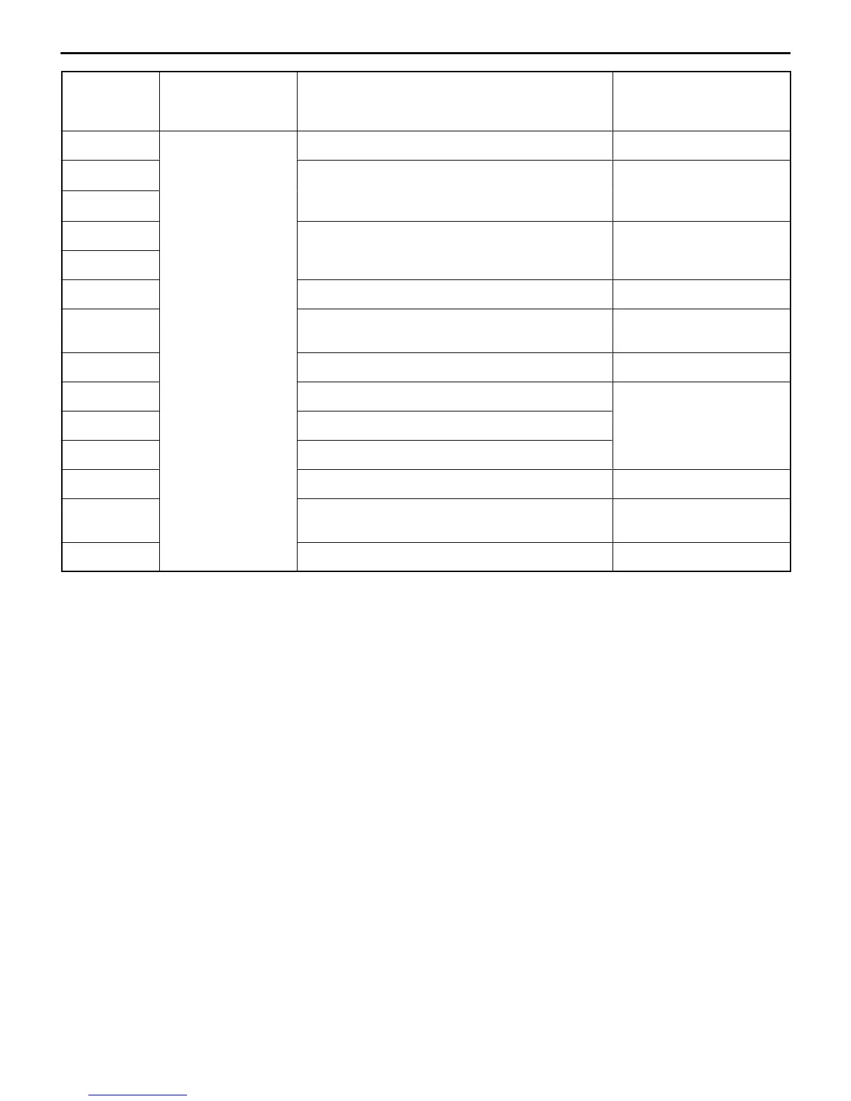
SRS-ECU
terminal No.
Harness connector
(No. of terminals,
colour)
Destination of harness Corrective action
1 to 4 21 pins, yellow – –
5 Body wiring harness → Clock spring → Air bag
’
Correct or replace each
6
.
clock spring.
7* Body wiring harness → Air bag module (Front
’
Correct or replace each
8*
passenger
s s
e
w
r
ng
arness.
9,10 – –
11 Body wiring harness → Diagnosis connector Correct or replace each
wiring harness.
12 – –
13 Body wiring harness → Junction block (fuse No.2) Correct or replace each
14 Body wiring harness → Junction block (fuse No.4)
w
r
ng
arness.
15 Body wiring harness → SRS warning lamp
16 to 19 – –
20 Body wiring harness → Earth Correct or replace each
wiring harness.
21 – –
NOTE
*: Vehicles with front passenger’s air bag
6. SRS components should not be subjected to hear over 93_C, so remove the SRS-ECU, air bag
module and clock spring before drying or baking the vehicle after painting.
7. Whenever you finish servicing the SRS, check warning lamp operation to make sure that the system
functions properly. (Refer to P.52B-14.)
8. Make certain that the ignition switch is LOCK (OFF) position when the MUT-II is connected or
disconnected.
9. If you have any questions about the SRS, please contact your local distributor.
NOTE
SERIOUS INJURY CAN RESULT FROM UNINTENDED AIR BAG DEPLOYMENT, SO USE ONLY
THE PROCEDURES AND EQUIPMENT SPECIFIED IN THIS MANUAL.