SRS – Air Bag Modules and Clock Spring
52B-26
REMOVAL AND INSTALLATION
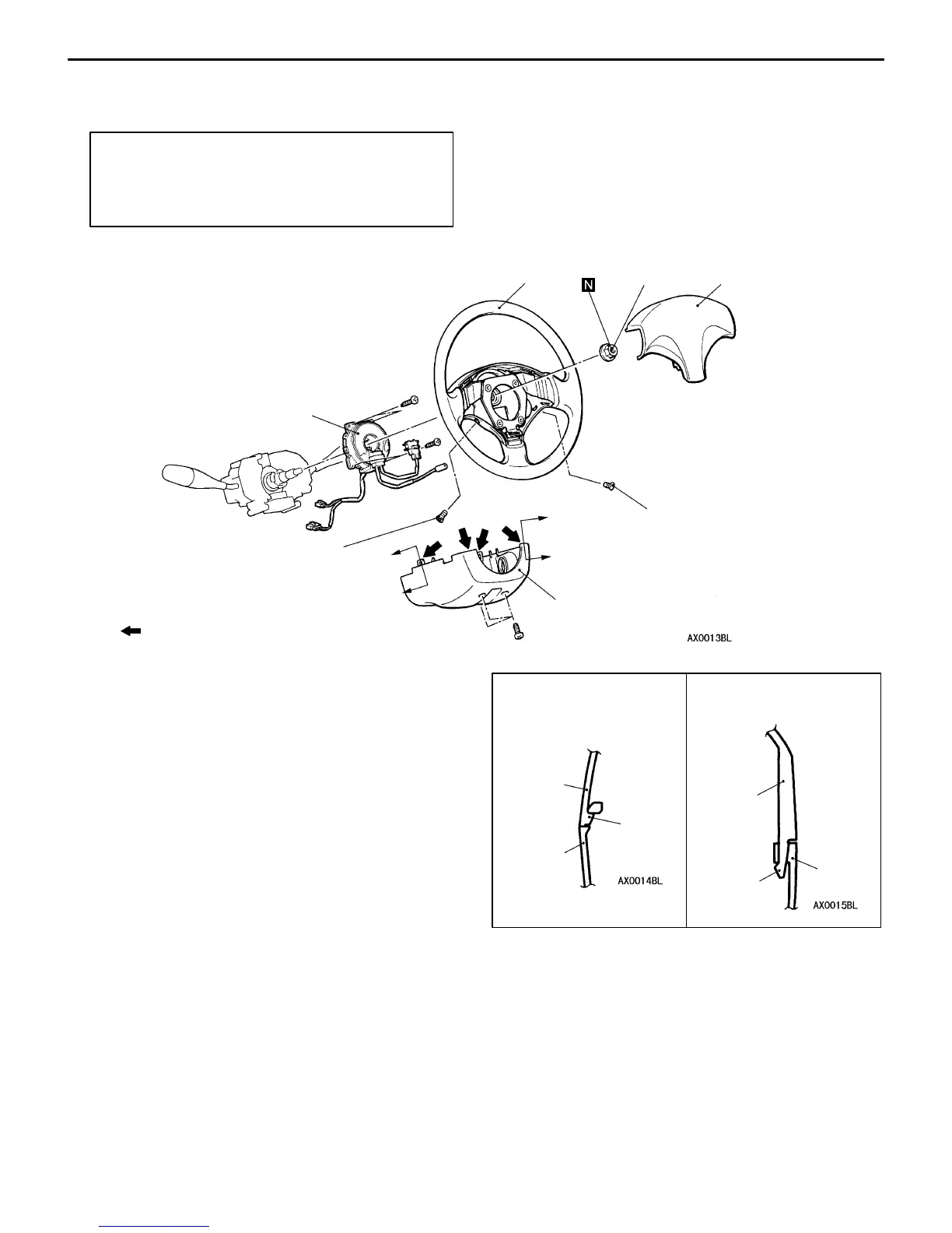
<Air bag module (driver’s side), clock spring>
Pre-removal Operation
D After setting the steering wheel and the front wheels
to the straight ahead position, remove the ignition
key.
D Battery negative (–) terminal disconnection
41 Nm
2
3
4
1
A
B
8.9 Nm
NOTE
: Indicates claw position.
Upper
column
cover
Claw
Section B – B
4
A
B
8.9 Nm
Section A – A
4
Upper
column
cover
Claw
Driver’s side air bag module
removal steps
AA" 1. Driver’s side air bag module
Clock spring removal steps
AA" 1. Driver’s side air bag module
AB" 2. Steering wheel
3. Lower column cover
AC" 4. Clock spring
Driver’s side air bag module
installation steps
"AADPre-installation inspection
1. Driver’s side air bag module
D Negative (–) battery cable connection
"DADPost-installation inspection
Clock spring installation steps
"AADPre-installation inspection
"BA 4. Clock spring
3. Lower column cover
"CA 2. Steering wheel
1. Driver’s side air bag module
D Negative (–) battery cable connection
"DADPost-installation inspection



 To Next Page