SRS – Air Bag Modules and Clock Spring
52B-31
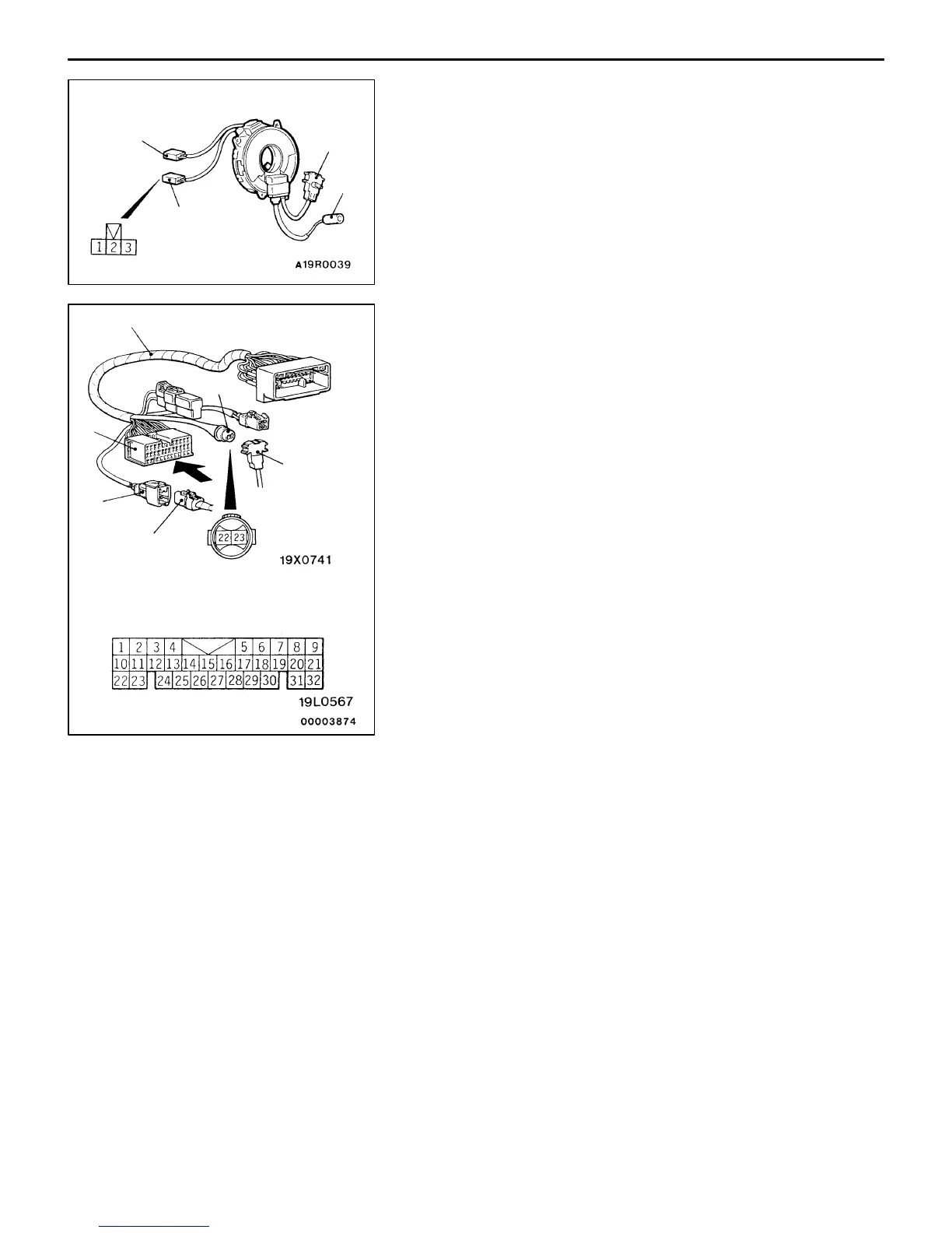
3. Check that there is continuity between terminal (3) of
the clock spring No.1 connector and the No. 2 connector.
4. Joint the No.3 connector and No.4 connector of the clock
spring to connector No.6 and connector No.4 respectively,
of the SRS check harness.
NOTE
When joining SRS check harness connector No.4 align
its white paint with the hollow portion of the No.4 connector
of the clock spring.
5. Check for continuity between terminal 22 and terminal
25, and terminal 23 and terminal 24, of SRS Check
Harness connector No. 5 using a digital multi-meter.
1
4
2
3
SRS check harness (MB991613)
Clock spring
connector 4
Clock spring
connector 3
View A
4
5
6
A
 Loading...