ENGINE – Cylinder Head and Valves
11-49
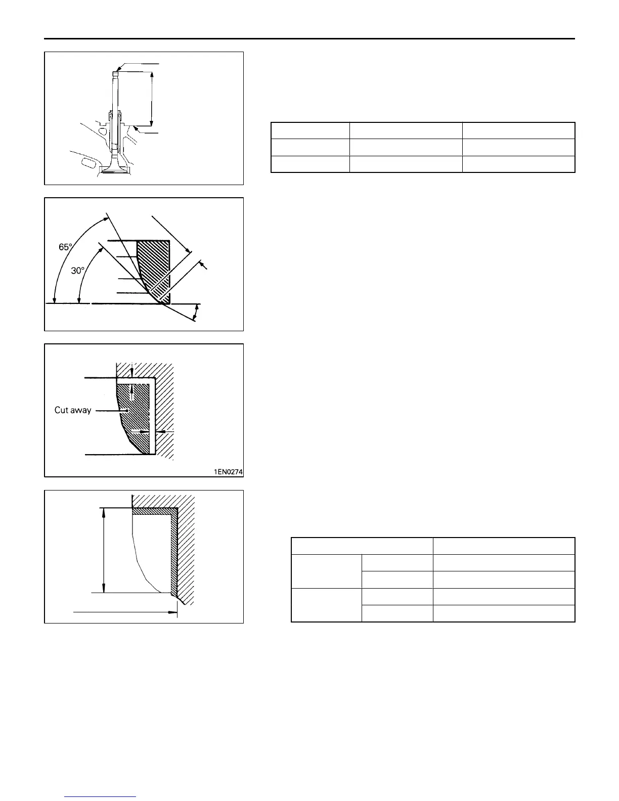
VALVE SEAT
Assemble the valve, then measure the valve stem projection
between the end of the valve stem and the spring seating
surface. If the measurement exceeds the specified limit,
replace the valve seat.
Item Standard value mm Limit mm
Intake 49.20 49.70
Exhaust 48.40 48.90
VALVE SEAT RECONDITIONING PROCEDURE
(1) Before correcting the valve seat, check for clearance
between the valve guide and valve and, if necessary,
replace the valve guide.
(2) Using the seat grinder, correct to obtain the specified
seat width and angle.
(3) After correcting the valve seat, lap the valve and valve
seat using lapping compound. Then, check the valve
stem projection (refer to VALVE SEAT in INSPECTION).
VALVE SEAT REPLACEMENT PROCEDURE
(1) Cut the valve seat to be replaced from the inside to thin
the wall thickness. Then, remove the valve seat.
(2) Rebore the valve seat hole in the cylinder head to a
selected oversize valve seat diameter.
Valve seat ring hole diameter
Item Standard value mm
Intake 0.30 O.S. 35.30 – 35.33
0.60 O.S. 35.60 – 35.63
Exhaust 0.30 O.S. 33.30 – 33.33
0.60 O.S. 33.60 – 33.63
(3) Before fitting the valve seat, either heat the cylinder head
up to approximately 250°C or cool the valve seat in liquid
nitrogen, to prevent the cylinder head bore from galling.
(4) Using a valve seat cutter, correct the valve seat to the
specified width and angle.
See “VALVE SEAT RECONDITIONING PROCEDURE”.
DEN0212
Valve stem end
Valve stem
projection
Spring seating
surface
6EN0491
0.9 – 1.3 mm
43.5° – 44°
0.5 – 1 mm
0.5 – 1 mm
1EN0275
Height of
seat ring
Oversize I.D.