4 - 12 4 - 12
MELSEC-
4 PROCEDURE UP TO DATA LINK
(2) Operating steps
The operating steps are shown below.
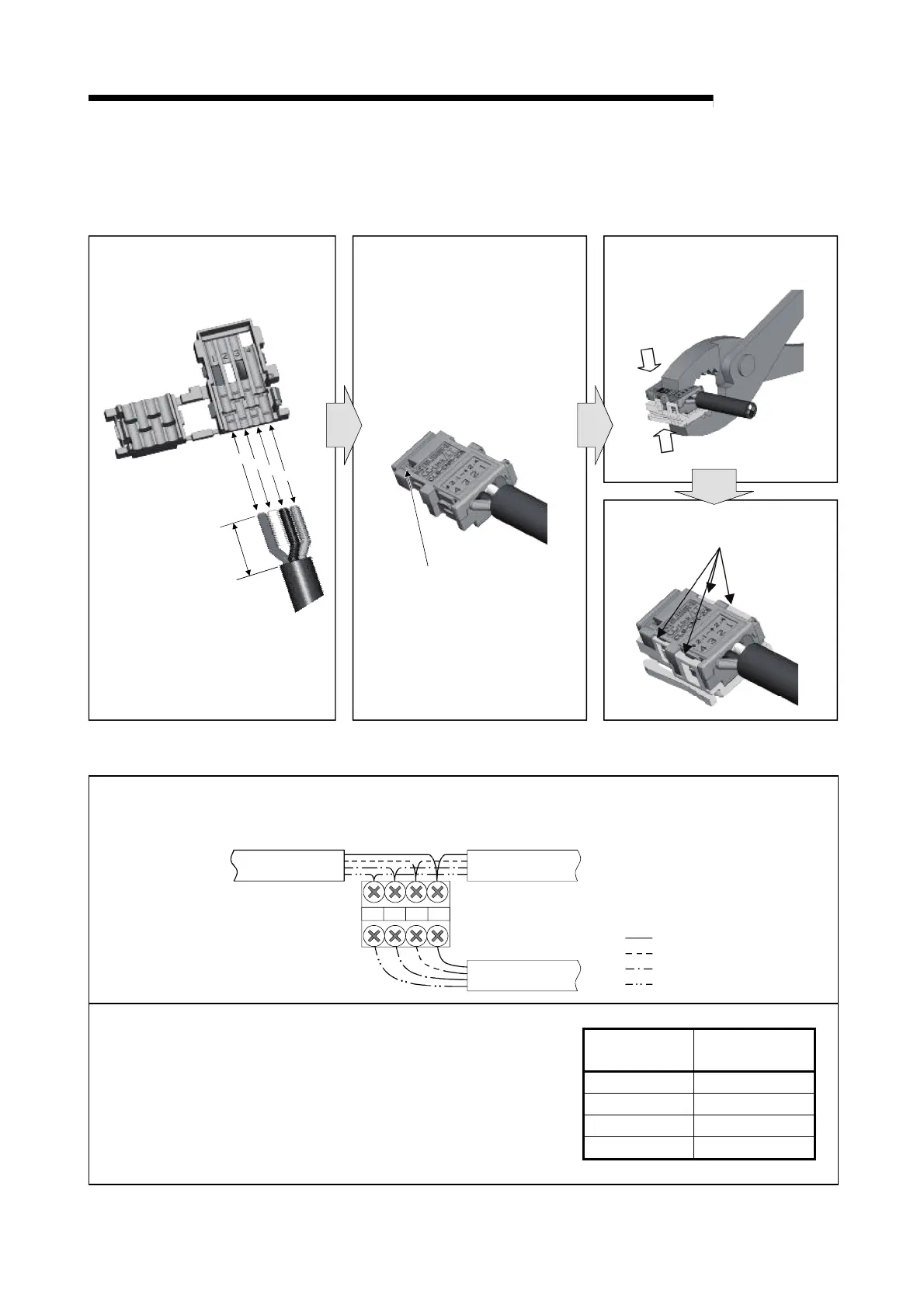
(a) Processing Cable End
1) Place each wire of the VCTF cable
or high flexible cable so that its wire
color matches the color inside the
cover.
If a red, white or black cable is
viewed through the hole, open
the cover and correct the wiring.
Incorrect wiring may cause failure
of the module.
3) Assemble the cover with the body
and press-fit them with pliers.
4) Verify that 4 latches are engaged.
Press-fitting is complete.
2) Close the cover so that the wires
are properly fitted. When the
wiring is correct, the green cable
can be viewed through the hole.
R
e
d
W
h
i
t
e
G
r
e
e
n
B
l
a
c
k
4
c
m
Green: Correct wiring
Red, white or black: Incorrect wiring
(b) T-Branch Processing (VCTF cable/High flexible cable)
5)-1 When using a terminal block for T-branching
When connecting VCTF cables or high flexible cables to the terminal block, cable colors must be
matched for each terminal.
DADB24G +24V
Red
White
Black
Green
VCTF cable/
High flexible cable
VCTF cable/
High flexible cable
VCTF cable/
High flexible cable
Dedicated flat
cable
VCTF cable/High
flexible cable
+24V Red
DA White
DB Black
24G Green
Note) When connecting a dedicated flat cable to the terminal block
(e.g. in a case where a VCTF cable is used for the trunk line
and dedicated flat cables for drop lines), each of "+24V",
"DA", "DB" and "24G" printed on the dedicated flat cable
must match the color of the VCTF or high flexible cable as
shown in the right table.
Split the dedicated flat cable into discrete "+24V", "DA", "DB"
and "24G" cables.
 Loading...


