App - 42 App - 42
MELSEC-Q
APPENDIX
(6) Redundant power supply module information
SD1780 to SD1789 are valid only for a redundant power supply system.
The bits are all 0 for a singular power supply system.
Number Name Meaning Explanation
Set by
(When set)
Corresponding
ACPU
D9
Applicable
CPU
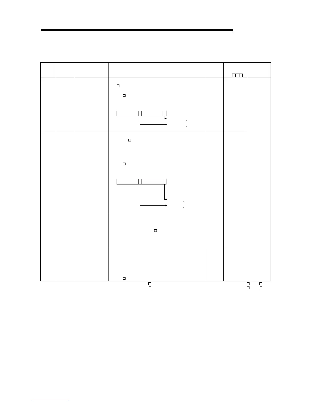
SD1780
Power
supply off
detection
status
Power supply off
detection status
• Stores the status of the redundant power supply module
(Q6
RP) with input power OFF in the following bit pattern.
• Stores 0 when the main base unit is not the redundant main base
unit (Q3
RB).
b0b7b8b15
toto
0
0
Input power OFF detection status
of power supply 1
Each bit
0: Input power ON status/ No
redundant power supply
module
1: Input power OFF status
SD1780
Input power OFF detection status
of power supply 2
1
1
S(Every
END)
New
SD1781
Power
supply
failure
detection
status
Power supply failure
detection status
• Stores the failure detection status of the redundant power supply
module (Q6
RP) in the following bit pattern. (The corresponding
bit is cleared to 0 when the input power to the faulty redundant
power supply module is switched OFF after detection of the
redundant power supply module failure.)
• Stores 0 when the main base unit is not the redundant main base
unit (Q3
RB).
Failure detection status of
power supply 2
b0b7b8b15
toto
00
Failure detection status of
power supply 1
Each bit
0: Redundant power supply
module failure not
detected/No redundant power
supply module
1: Redundant power supply
module failure detected
(Detectable for redundant
power supply module only)
SD1781
1
1
S(Every
END)
New
SD1782
Momentary
power
failure
detection
counter for
power
supply 1*1
Momentary power
failure detection count
for power supply 1
S(Every
END)
New
SD1783
Momentary
power
failure
detection
counter for
power
supply 2*1
Momentary power
failure detection count
for power supply 2
• Counts the number of times of momentary power failure of the
power supply 1/2.
• Watches the status of the power supply 1/ 2 mounted on the
redundant main base unit (Q3
RB) and counts the number of
times of momentary power failure.
• When the CPU module starts, the counter of the power supply 1/
2 is cleared to 0.
• If the input power to one of the redundant power supply modules
is turned OFF, the corresponding counter is cleared to 0.
• The counter is incremented by 1 every time the momentary
power failure of the power supply 1/ 2 is detected.
(0 to 65535: When the count exceeds 65535, it starts with 0.)
• Stores 0 when the main base unit is not the redundant main base
unit (Q3
RB).
S(Every
END)
New
QnPRH
Remote
*1: The "power supply 1" indicates the redundant power supply module (Q6 RP) mounted on the POWER 1 slot of the redundant base unit (Q3 RB/Q6 RB).
The "power supply 2" indicates the redundant power supply module (Q6
RP) mounted on the POWER 2 slot of the redundant base unit (Q3 RB/Q6 RB).
 Loading...


