38
3 Specific Usage Applications
No. 99MAF029B
3.2
Judging the Tolerance
By setting the upper and lower tolerance limits in advance, the acceptability judgment can be
automatically performed. The acceptability judgment will be displayed on the LED and the LCD screen,
meaning it can be easily determined whether the value falls within the tolerance range.
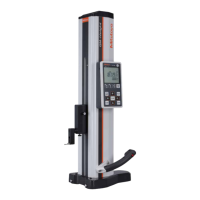
Operation panel
Red: Upper tolerance limit exceeded.
Orange: Lower tolerance limit exceeded.
Green: Within the tolerance range.
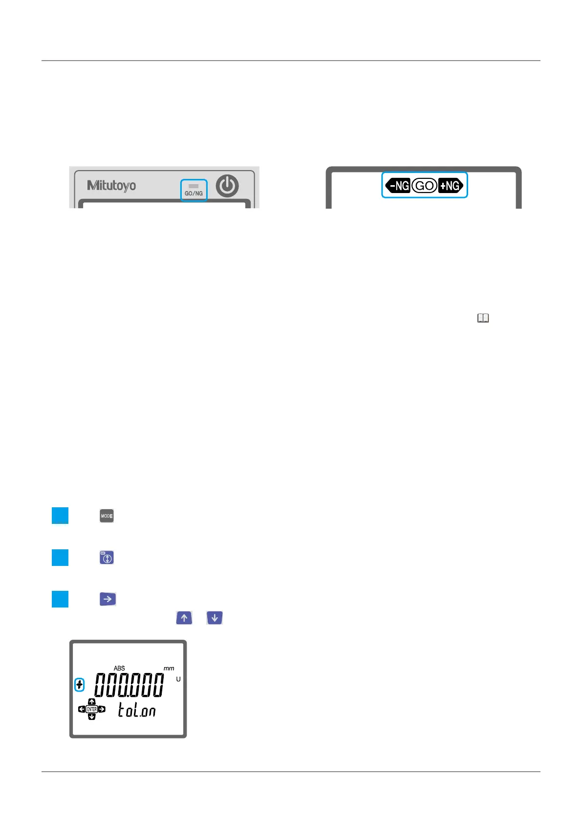
LCD screen
[+NG]: Upper tolerance limit exceeded.
[-NG]: Lower tolerance limit exceeded.
[GO]: Within the tolerance range.
To perform the acceptability judgment automatically, register the upper and lower tolerance limits, and
then enable the acceptability judgment function.
Tips
You can change the length of time that the LED is lit. For details about changing the settings, "3.8
Setting the LED Lighting Time" (page 46)
3.2.1 Setting the Upper and Lower Limits
For example, the procedure for setting the upper [+0.010 mm] and lower [–0.005 mm] tolerance limits
is explained below.
Tips
• The set values are retained in memory even if the power is turned off.
• Be sure to set the upper limit value to a numeric value larger than the lower limit value. If a smaller
value is set, there will be an error.
1
Press .
»
Characters and icons will be displayed in the bottom row of the LCD screen.
2
Press to select [TOL.] (tolerance setting).
»
[U] and the current upper limit will be displayed on the LCD screen.
3
Press to make [+] flash.
If [–] is displayed, press or to change it to [+].

 Loading...