Instruction Manual #122162 12
Reference Port this port is not currently used on models supplied with this manual. A
limited number of models are available with the reference port operational to allow for differential
pressure control relative to a pressure other than atmosphere.
CD-20 Output Port provides a means for connecting the CD-20 to the facility exhaust.
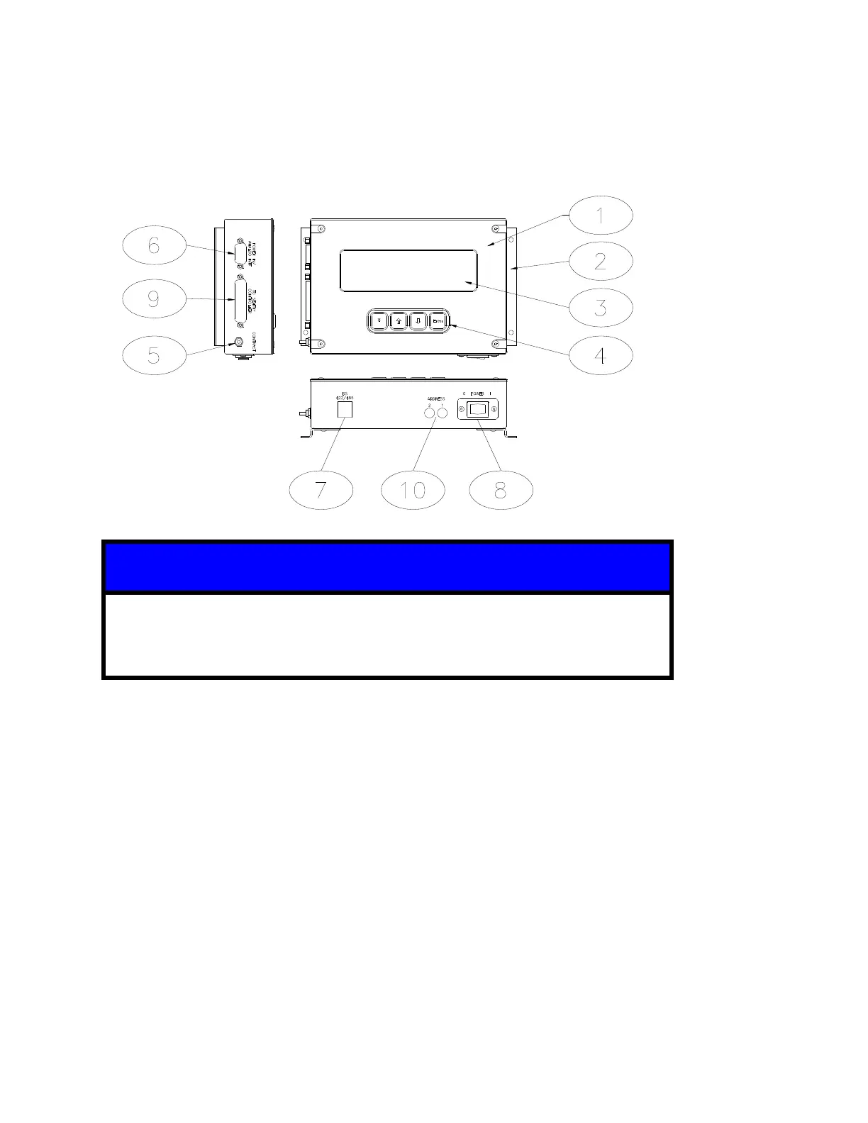
2.1.2 SENTRY TIM-100/120
A TIM-100 is shown above. Except for items 3 and 4, the descriptions listed
also apply to the TIM-120. Access to the display and keypad on a TIM-120 is
provided through the use of a Program Module available separately.
SENTRY TIM-100/120 is a microprocessor-based interface used in conjunction with the
Sentry 1510. The TIM-100/120 provides the user with the ability to interface with the SENTRY
1510 controller through direct keypad input or through electronic communication from the
process equipment.
Mounting Brackets are used to mount the TIM-100/120 to the process equipment.
Display provides a real time read-back of pressure control. It also allows the user to view
and change the menu parameters.
Keypad contains the four keys used to navigate and change the menu tree and parameters.
Contrast Knob allows the user to adjust the display contrast.
Power/Interface Port accepts the power cable (power supply) or power and interface cable.
RS 422/485 Port accepts the optional serial communication cable.
On/Off Switch is an on/off rocker connected to a fuse. The fuse acts as a safety cut-off
device by detecting over-current situations and cutting power to the TIM-100/120.
SENTRY Port accepts the TIM-100/120 to SENTRY 1510 controller cable.
Address Switches are used to set the base address of the TIM-100/120 when using the RS
422/485 communication port.
 Loading...


